FRANÇAIS
DEUTSCH
ESPAÑOL
ÐÓÑÑÊÈÉ
23
COD. 104060 Rev.1
ENGLISH
MOUNTING
instructions for mounting tyres
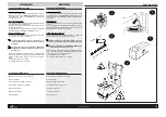
» Lubricate the tyre beads (fig.22).
» Rest the tyre on the rim.
» Lower the head column and move the head into the
working position resting the bead on the edge of the
head and under the tongue.
» Rotate the chuck pressing the inverter pedal and tak-
ing care to insert the bead into the central rim-well so
as to avoid over straining the bead. This operation
should be assisted by pushing on the tyre with the
hands (fig.23).
» Position the rim with the hole for the inner-tube valve
at 90º to the head. Insert the inner-tube (unnecessary
with tubeless tyres).
» Position the upper roller (with mechanical hand) and
the lower roller (with mechanical hand) as close as
possible to the rim flange (see control panel) (fig.24).
» Position the helper so that it keeps the tyre in the rim-
well (fig.25).
» Rotate the chuck pressing the inverter pedal until the
tyre is fully inserted into its seating (fig.26-27).
» Raise the head column, move away the bead breaking
rollers and helper and then press the pedal to release
the rim.
» Inflate using the inflation gun (fig.28)or with the tube-
less inflation kit (fig.29)(depending on the type of tyre)
up to the correct pressure.
» Release the rim from the flange by unscrewing the wing
nut and removing the fixing cone.
» Raise the tyre using the lift control pedal and return the
wheel to the ground.
ALUMINIUM AND LIGHT ALLOY RIMS
To mount tyres onto aluminium or light alloy rims, follow
the normal mounting procedure (described above).
Important
: with low-profile tyres (45 / 40 / 35 ) the mount-
ing of the 2nd bead might prove difficult. If so proceed as
follows:
»
Move the upper roller to the side of the tyre.
»
Rotate the chuck plate until mounting is complete.
To release the rim:
»
Raise the head column.
»
Unscrew (and remove) the fixing screws and free the
rim.
MONTAGE
Instructions pour les opérations de montage du pneu
» Lubrifier les talons du pneu (fig.22);
» Appuyer le pneu sur la jante;
» Faire baisser la colonne, amener la tourelle à la posi-
tion de travail en appuyant le talon sur le bord de la
tourelle sous la languette;
» Faire tourner l’autocentreur en pressant la pédale de
l’inverseur et en prenant soin de faire entrer le talon
dans la gorge centrale de la jante, afin d’éviter de
déformations du talon (Rmq:
pour favoriser cette
opération il est conseillé de presser sur le pneu avec
les mains
)(fig.23).
» Positionner la jante, avec le trou pour la soupape de la
chambre à air à environ 90° de la tourelle; introduire la
chambre à air (opération non nécessaire pour les pneus
tubeless).
» Répéter les opérations dès le début (voir plus haut)
pour faire entrer le 2
ème
talon.
» Positionner le rouleau supérieur et le rouleau inférieur
(les deux avec le manipulateur) le plus près possibile
du bord de la jante (voir la console de commande)
(fig.24);
» Positionner l’assistant de façon qu’il maintienne le pneu
dans la gorge (fig.25);
» Faire tourner l’autocentreur en pressant la pédale de
l’Inverseur jusqu’à l’introduction complète du pneu
dans le logement (fig.26-27).
» Faire monter la colonne de la tourelle, éloigner les rou-
leaux détalonneurs et l’assistant et presser la pédale
pour débloquer la jante.
» Exécuter le gonflage avec le pistolet de gonflage (fig.28)
ou le kit gonfie tubeless (fig.29) (selon le genre de
pneu) jusqu’à la pression correcte.
» Débloquer la jante de la bride en desserant l’écrou
papillon et en retirant le cône de fixation.
» Lever le pneu par la commande pédale de l’élévateur
et poser la roue par terre.
JANTES EN ALU ET EN ALLIAGE LEGER
Pour le montage des pneus sur les jantes en alu ou en
alliage léger suivre les instructions prévues pour le mon-
tage “normal” (voir ci-dessus).
Attention
: Dans le cas où, à cause du pneu baissé (45 /
40 / 35 ) le montage du 2
ème
talon résulterait difficile, procéder
comme suit:
» Approcher le rouleau supérieur au côté du pneu;
» Faire tourner le plateau autocentreur jusqu’à avoir
effectué le montage;
Pour débloquer la jante:
» Faire monter la colonne de la tourelle;
» Dévisser (et ensuite sortir) la vis de fixation et dégager
la jante.
MONTAGE
Anweisungen für die Montage des Reifens
»
Die Reifenwülste schmieren (Abb.22).
»
Den Reifen auf der Felge ablegen.
»
Die Drehkopfsäule absenken, den Drehkopf in
Betriebsstellung bringen, indem die Wulst auf dem Rand
des Drehkopfs und unter dem Schutzkeil abgelegt wird.
»
Das selbstzentrierende Spannfutter durch Betätigung
des Umkehrpedals drehen, dabei darauf achten, dass
die Reifenwulst in die Felgennut eindringt, um eine
Zerfaserung der Reifenwulst zu verhindern. Um diesen
Arbeitsgang zu erleichtern, ist es ratsam, durch
Drücken mit den Händen auf den Reifen nachzuhelfen
(Abb.23).
»
Die Felge mit dem Ventilloch der Luftkammer in einem
Winkel von ca. 90 º zum Drehknopf ausrichten, die
Luftkammer einsetzen (Dieser Arbeitsgang ist bei
schlauchlosen Reifen nicht notwendig).
»
Die obere Rolle (mit Manipulator) und die untere Rolle
(mit Manipulator) so nah wie möglich am Felgenrand
positionieren (siehe Steuerpult) (Abb.24).
»
Die Hilfsvorrichtung so positionieren, dass der Reifen
im Felgenkanal bleibt (Abb.25).
»
Das selbstzentrierende Spannfutter durch Betätigung
des Umkehrpedals drehen, bis sich der Reifen
vollständig in seinen Sitz einfügt (Abb.26-27).
»
Die Drehkopfsäule anheben, die Abdrückrollen und die
Hilfsvorrichtungen in Abstand vom Reifen bringen und
dann die Pedale betätigen, um die Felge festzustellen.
»
Jetzt den Reifen je nach Reifenart mit der Pumppistole
(Abb.28) oder mit dem Set für schlauchlose Reifen (Kit
Gonfiatubeless) aufpumpen (Abb.29), bis der richtige
Druck erreicht ist.
»
Die Felge aus dem Flansch lösen, indem die
Flügelmutter gelöst wird und den Befestigungskonus
entfernen.
»
Den Reifen mit dem Bedienpedal für die Hubvorrichtung
anheben und auf dem Boden ablegen.
ALUMINIUM- UND LEICHTMETALLFELGEN
Für die Montage von Reifen auf Aluminium- oder
Leichtmetallfelgen den Anleitungen für die gewöhnliche
Montage folgen (wie oben beschrieben).
Vorsicht!:
Sollte sich aufgrund des abgesenkten Reifens
(45/40/35) die Montage der zweiten Reifenwulst als
schwierig erweisen, wie folgt vorgehen:
»
Die obere Abdrückrolle an der Reifenseite positionieren:
»
Den Spannteller drehen, bis die Montage ausgeführt
wurde.
Um die Felge aus der Befestigung zu lösen:
»
Die Drehkopfsäule anheben.
»
Die Befestigungsschrauben lösen (und daraufhin
entfernen) und die Felge freigeben.
MONTAJE
Instrucciones para las operaciones de montaje del
neumático
»
Lubricar los talones del neumático (fig.22);
»
Apoyar el neumático en la llanta;
»
Bajar la barra de la torreta, llevar la torreta a la posición
de trabajo apoyando el talón sobre el borde de la misma
y bajo la lengüeta;
»
Hacer girar el autocentrante pisando el pedal de
inversión asegurándose de hacer entrar el talón en el
canal central de la llanta, a fin de eliminar las
deformaciones del talón. Para favorecer esta
operación, se aconseja hacer presión sobre el
neumático con las manos (fig.23).
»
Colocar la llanta con el orificio para la válvula de la
cámara de aire aproximadamente a 90° grados de la
torreta; introducir entonces la cámara de aire (operación
no necesaria en caso de neumáticos tubeless).
»
Situar los rodillos superior e inferior (ambos con
manipulador) lo más cerca posible del borde de la llanta
(ver consola de control) (fig.24);
»
Situar el asistente de manera que mantenga el
neumático en el canal (fig.25);
»
Hacer girar el autocentrante pisando el pedal de
inversión hasta introducir el neumático por completo
en su alojamiento (fig.26-27).
»
Levantar la barra de la torreta, separar los rodillos
destalonadores y el asistente y pisar el pedal para
soltar la llanta.
»
Inflar hasta la presión adecuada, ya sea con la pistola
infladora (fig.28) o con el kit para inflado de tubeless
(fig.29) (según el tipo de neumático).
»
Soltar la llanta de la brida aflojando la palomilla y
retirando el cono de sujeción.
»
Levantar el neumático accionando el pedal elevador y
descargar la rueda en el suelo.
LLANTAS EN ALUMINIO Y ALEACIÓN LIGERA
Para montar neumáticos en llantas de aluminio o aleación
ligera, seguir las instrucciones de montaje normal (antes
descritas).
Atención:
En caso de que, por tratarse de un neumático
rebajado (45 / 40 / 35 ), el montaje del 2º talón presentase
dificultades, proceder como se indica a continuación:
»
Acercar el rodillo superior al lado del neumático;
»
Girar el plato autocentrante hasta completar el montaje;
Para desbloquear la llanta:
»
Levantar la barra de la torreta;
»
Destornillar (y después quitar) los tornillos de fijación
y dejar libre la llanta.
ÌÎÍÒÀÆ
Èíñòðóêöèÿ îïåðàöèé ìîíòàæà øèíû
»
Ñìàçàòü áîðò øèíû (ðèñ.22);
»
Ïîëîæèòü øèíó íà äèñê;
»
Îïóñòèòü ðàáî÷óþ ñòîéêó, ïðèâåñòè ãîëîâêó
ðàáî÷åé ñòîéêè â ðàáî÷åå ïîëîæåíèå,
óñòàíîâèòü áîðò øèíû íà êðàé ãîëîâêè ïîä
ÿçû÷êîì;
»
Íàæàòèåì ïåäàëè èíâåðòîðà âðàùàòü
ñàìîöåíòðèðóþùèéñÿ ñòîë, îáðàùàÿ âíèìàíèå
íà òî, ÷òîáû áîðò ïîêðûøêè âîøåë â
öåíòðàëüíûé ïàç îáîäà, ïðåäîòâðàùàÿ òàêèì
îáðàçîì ïîâðåæäåíèå áîðòà. Äëÿ îáëåã÷åíèÿ
äàííîé îïåðàöèè ðåêîìåíäóåì íàæèìàòü
ðóêàìè íà øèíó (ðèñ.23).
»
Óñòàíîâèòü îáîä ñ îòâåðñòèåì äëÿ âåíòåëÿ
êàìåðû ïîä óãëîì 90 ãðàäóñîâ ïî îòíîøåíèþ ê
ðàáî÷åìó ñòîÿêó, ïîñëå ÷åãî ââåñòè âîçäóøíóþ
êàìåðó (äëÿ áåñêàìåðíûõ øèí ýòà îïåðàöèÿ íå
òðåáóåòñÿ).
»
Ïîäâåñòè âåðõíèé ðîëèê (ìàíèïóëÿòîðîì) è
íèæíèé ðîëèê (ìàíèïóëÿòîðîì) êàê ìîæíî
áëèæå ê êðàþ äèñêà (ñì. ïóëüò
óïðàâëåíèÿ)(ðèñ.24);
»
Ðàñïîëîæèòü óñòðîéñòâî “helper“ òàêèì
îáðàçîì, ÷òîáû îíî óäåðæèâàëî øèíó â êàíàëå
»
Íàæàòèåì ïåäàëè èíâåðòîðà âðàùàòü
ñàìîöåíòðèðóþùèéñÿ ñòîë äî ïîëíîé
óñòàíîâêè øèíû íà ìåñòî (ðèñ.25);
»
Ïîäíÿòü ðàáî÷óþ ñòîéêó, óäàëèòü
ðàçáîðòîâî÷íûå ðîëèêè è óñòðîéñòâî “helper“
è çàòåì íàæàòü íà ïåäàëü äëÿ ðàçáëîêèðîâêè
äèñêà (ðèñ.26-27);
»
Ïðîèçâåñòè íàêà÷êó øèíû äî íóæíîãî äàâëåíèÿ
ïîñðåäñòâîì íàñîñíîãî ïèñòîëåòà èëè
óñòðîéñòâà íàêà÷èâàíèÿ áåñêàìåðíûõ øèí (â
çàâèñèìîñòè îò òèïà øèíû) (ðèñ.28-29);
»
Ðàçáëîêèðîâàòü äèñê ñ ôëàíöà îòêðóòèâ
êðûëü÷àòóþ ãàéêó è óäàëèâ ôèêñèðóþùèé êîíóñ.
»
Ïðè ïîìîùè ïîäúåìíèêà ïîäíÿòü êîëåñî è
îïóñòèòü åãî íà çåìëþ..
ÀËÞÌÈÍÈÅÂÛÅ ÄÈÑÊÈ È ÄÈÑÊÈ ÈÇ ËÅÃÊÎÃÎ
ÑÏËÀÂÀ
Äëÿ äåìîíòàæà øèí óñòàíîâëåííûõ íà àëþìèíèåâûõ
äèñêàõ èëè äèñêàõ èç ëåãêîãî ñïëàâà ïðèäåðæèâàòüñÿ
îñíîâíûõ èíñòðóêöèè ïî ìîíòàæó
(âûøåîïèñàííûõ).
Âíèìàíèå!
 òåõ ñëó÷àÿõ, êîãäà ïî ïðè÷èíå
ñíèæåííûõ øèí (45/40/35) ìîíòàæ
II-îãî
áîðòà
ïðåäñòàâëÿåò òðóäíîñòè, äåéñòâîâàòü ñëåäóþùèì
î á ð à ç î ì :
»
Ïðèáëèçèòü âåðõíèé ðîëèê ê áîêîâîé ñòîðîíå
øèíû;
»
Âðàùàòü ñàìîöåíòðèðóþùèé ñòîë äî ïîëíîãî
äåìîíòàæà
Äëÿ ðàçáëîêèðîâêè äèñêà:
»
Ïîäíÿòü ñòîéêó ðàáî÷åé ãîëîâêè;
»
Îòâèíòèòü (è çàòåì ñíÿòü) ôèêñèðóþùèé âèíò è
îñâîáîäèòü äèñê.
Summary of Contents for FALCO AF 2500
Page 45: ...N 104036 Rev 0 OPTIONAL...
Page 46: ...N 104362 01 Rev 0 FALCOAF 2500...
Page 47: ...N 104362 02 Rev 0 FALCOAF 2500...
Page 48: ...N 104362 03 Rev 0 FALCOAF 2500...
Page 49: ...N 104362 04 Rev 0 FALCOAF 2500...
Page 50: ...N 104362 05 Rev 0 FALCOAF 2500...
Page 51: ...N 104361 01 Rev 0 FALCOAF 2500...
Page 52: ...N 104361 02 Rev 0 FALCOAF 2500...
Page 53: ...N 104361 03 Rev 0 FALCOAF 2500...
Page 54: ...N 104361 04 Rev 0 FALCOAF 2500...
Page 55: ...N 104361 05 Rev 0 FALCOAF 2500...
Page 56: ...N 104338 01 Rev 0 FALCOAF 2500...
Page 57: ...N 104338 02 Rev 0 FALCOAF 2500...
Page 58: ...N 104338 03 Rev 0 FALCOAF 2500...
Page 59: ...N 104338 04 Rev 0 FALCOAF 2500...
Page 60: ...N 104338 05 Rev 0 FALCOAF 2500...
Page 61: ......


