


ENGLISH
DEUTSCH
ESPAÑOL
13
COD. 103202 Rev.4
STANDARDZUBEHÖR
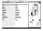
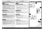
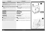
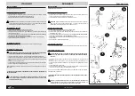
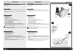
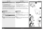
FILTERGRUPPE FR + L (Abb. 11)
Sie besteht aus einem Filter zur Beseitigung möglicher Unreinheiten und übermäßiger Luftfeuchtigkeit,
aus einem Druckvermin-derer zur Regulierung des richtigen Bedie-nungs-drucks und aus einem
Schmierer, der Öl in die Luftdruckanlage sprüht
Mit der WULSTHEBERSTANGE (Abb. 12)
kann der Reifenwulst angehoben und während des Abmontiervorgangs auf den Drehkopf gehoben
werden.
Dieses Werkzeug ermöglicht die Lenkung der ‘Kanalisierung’ des Wulstes bei der Reifenmontage.
Die Wulstheberstange wird nach der Installation des Geräts in den Schlitz des Wulstheberhalters seitlich
vom Gerät gesteckt.
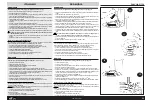
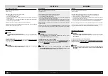
Der DOSENHALTERRING (Abb. 13)
hält die Dose des Schmierfetts, das während des Reifenmontiervorgangs verwendet werden sollte.
Nach Instal-la-tion des Geräts wird der Dosenhalterring an der Tragsäule befestigt (Abb. 13).
Zusätzlich wird ein Pinsel zum Ein-schmie-ren des Reifenwulstes geliefert.
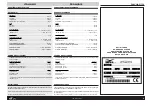
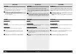
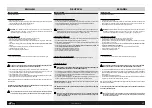
Diese Schachtel enthält das Standardzubehör (Abb. 14) und steckt in der Verpackung
des Geräts (siehe Anleitungen für das Auspacken).
Beachten Sie bitte: immer genauestens die WARNUNGSZEICHEN die in Form von
Aufklebern auf dem Gerät angebracht sind (Abb. 15)
Sollte sich einer oder mehrere der Aufkleber vom Gerät gelöst haben oder beschädigt sein, fordern Sie
bitte die jeweiligen Aufkleber vermittels eines entsprechenden Kodes bei unserem Ersatzteildienst SICAM
an:
(a) - Aufkleber “Drehkopf” (Kode Nr. 100982 )
(b) - Aufkleber “Spannung” (Kode Nr. 100789)
(c) - Aufkleber “Wulstheber “ (Kode Nr.100983)
(d) - Aufkleber “kippbare Tragsäule” (Kode Nr.100776)
ZUSÄTZLICHES ZUBEHÖR
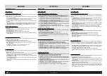
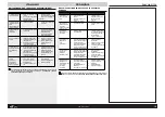
SCHUTZVORRICHTUNGEN FÜR LEGIERTE REIFENFELGEN
Es handelt sich hierbei um spezielle Schutz-vorrichtungen, die auf Reifenfelgen in Leicht-le-gierung
anzubringen:
- Schutz für Rinnenschiene 19" (Abb. 16a) -vierteilig.
- Schutz für Drehkopfkeil (Abb. 16b) -einteilig.
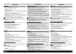
SICHERHEITSVORRICHTUNG
Um den Bediener des Geräts beim Aufpumpen des Reifens auf der Selbstzentriererplatte vor potentiellen
Gefahren zu schützen, verfügt das Gerät über eine Druckbeschränkungsdüse bei 3,5 bar und über
eine Höchstdruckdüse, die bis 4 bar reicht
Das Aufpumpen des Reifens ist potentiell gefährlich! Um den Reifen auf der
Selbstzentriererplatte unter bestmöglichen Sicherheits-bedingungen aufzupumpen, raten
wir Ihnen, die entsprechenden SICHERHEITSGURTE anzufordern, einzubauen und auch
zu verwenden (Siehe Abb. 17)
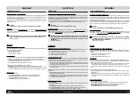
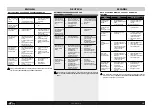
VORRICHTUNG “ANSCHLÜSSE 8” (vier-teilig): damit können Sie kleinere Reifen abmontieren (z.B.
Reifen von Schubkarren, Gartengeräten, beweglichen Golfgeräten usw. (Abb. 18)
VORRICHTUNG “SPEZIALANSCHLÜSSE 17-21” (vierteilig): diese braucht man, um auf besonderen
Reifenfelgen von 17" bis 21" mit einem über den Felgenrand übertretenden Außen-flansch zu operieren
(Abb. 19).
VORRICHTUNG “ANSCHLÜSSE FÜR KRAFTRÄDER”: damit kann man Reifen von Motorrädern
von 24" ab- und auf-montieren (Abb. 20). Eine Polyurethan-verkleidung schützt den Felgen vor Kratzern.
Die “Anschlüsse für Krafträder” (vierteilige Serie) sind einfach anzubringen, es genügt, sie auf die
Schienen der Selbst-zen-trierer-platte zu setzen und mit den entsprechenden Schrauben
festzuschrauben.
ACCESORIOS DE EQUIPO
UNIDAD FILTRO FR + L (fig. 11)
La Unidad se compone de un Filtro para eliminar las eventuales contaminaciones y la excesiva humedad
presente en el aire, de un Reductor de presión para el correcto ajuste de la presión de trabajo y de un
Lubrificador para pulverizar aceite en la instalación neumática.
PALANCA LEVANTA-TALONES (fig.12)
Es una herramienta necesaria para levantar el talón del neumático y llevarlo sobre la torre durante las
fases de desmontaje.
Consiente luego de guiar el “encauzamiento” del talón mismo en la fase de montaje del neumático.
La palanca levanta-talones, una vez instalada la máquina, debe colocarse en la ranura de apoyo del
destalonador, al lado de la máquina.
ANILLO PORTA-TARRO (fig.13)
Sirve de soporte al tarro de la grasa que se debe utilizar durante la fase de montaje de los neumáticos.
Después de la instalación de la máquina, el anillo debe fijarse a la columna como muestra la fig. 13.
Además, está suministrado un pincel para engrasar el talón del neumático.
La caja que contiene los accesorios de equipo (fig. 14) está en el embalaje de la máquina
(véase instrucciones para desembalar).
Tenga siempre mucho cuidado con las SEÑALES DE SEGURIDAD representadas con
adhesivos adecuados y aplicados en la máquina (fig. 15).
En caso de pérdida o deterioro de una o más etiquetas adhesivas aplicadas en la máquina, dirígase
inmedia-ta-mente al servicio”piezas de repuesto” SICAM para requerirla/las indicando el número de
código relativo:
(a) - etiqueta “torre” (cód. n. 100982)
(b) - etiqueta “tensión” (cód. n. 100789)
(c) - etiqueta “destalonador” (cód.n.100983)
(d) - etiqueta “columna volcable” (cód.n.100776)
ACCESORIOS OPCIONALES
PROTECCIONES PARA LLANTAS DE ALEACION
Son especiales protecciones predispuestas para actuar sobre llantas de aleación ligera:
- Protecciones Recorridos para cuñas de 19" (fig. 16a) - 4p
- Protección Lengüeta de la torre (fig. 16b) - 1p
DISPOSITIVO DE SEGURIDAD
Para proteger al operador de los peligros que podrían proceder del hincha-miento del neumático sobre
el plato del autocentrado, la máquina está dotada de una válvula limitadora de la presión de trabajo
ajustada a 3,5 bar y de una válvula de presión máxima ajustada a 4 bar.
El hinchamiento del neumatico es una operacion potencialmente peligrosa!
Para hinchar el neumatico sobre el plato del autocentrado en condiciones de seguridad
es obligatorio utilizar los apropiados CINTURONES DE SEGURIDAD (fig. 17)
DISPOSITIVO “CONEXIONES 8” (4 p.): permite el desmontaje de los neumáticos de pequeñas
dimensiones como por ejemplo los neumáticos de carretillas, de herramientas para el jardín, de medios
móviles para el golf, etc.(fig.18).
DISPOSITIVO “CONEXIONES ESPECIALES 17-21” (4 p.): sirve para obrar sobre llantas particulares
de 17" a 21" con brida exterior más saliente con respecto al borde de la llanta (fig. 19).
DISPOSITIVO “CONEXIONES MOTOS”: es un dispositivo que consiente desmontar y montar los
neumáticos de las ruedas de motocicletas de 24" (fig. 20). Una capa de poliuretano protege de posibles
rayas la llanta misma. Las “conexiones motos” (serie de 4 p.) se montan con facilidad: basta con
introducirlas en los recorridos del autocentrado y bloquearlas con los tornillos apropiados.
ACCESSORIES PROVIDED
FILTER UNIT FR + L (fig.11)
This unit is composed of a filter for the elimination of impurities or excessive humidity in the air, a
pressure reducer for maintaining the correct operating air pressure, and a lubricator for atomizing oil
into the pneumatic system.
BEAD LIFTING LEVER (fig.12)
This is a tool required for lifting the tyre bead onto the head during the demounting stage.
It is also used to guide the channelling of the bead during tyre mounting.
Once the machine has been installed the lever is kept in the ring in the bead-breaker support, on the
side of the machine.
LUBRICATION TIN (fig.13)
Once the machine has been installed the lubrication tin is fitted in the position indicated (see fig. 13) on
the side cover of the machine.
The box containing the accessories supplied (fig. 14) is contained in the machine pack-
ing (see unpacking instructions).
Always pay careful attention to the WARNING SIGNS shown on adhesives applied to the
machine (fig.15).
If one or more of the warning signs disappears or shows signs of deterioration, you are requested to
order a replacement from SICAM’s “Spare Parts” service, making use of the relevant code number:
(a) -”head” adhesive (code no. 100982 )
(b) - “electrical tension” adhesive (code no. 100789)
(c) - “bead-breaker” adhesive (code no.100983)
(d) -”tilting column” adhesive (Code no.100776)
ACCESSORIES ON REQUEST
ALLOY RIM PROTECTORS
These are special protectors suitable for working on light alloy:
- Track protectors for the 19" jaws (fig. 16a). 4 parts.
- Head tongue protector (fig. 16b). 1 part.
INFLATION SAFETY DEVICE
The machine is fitted with a pressure limiting valve set at 3.5 bar and a maximum pressure valve
set at 4 bar. These are designed to protect the operator from potential danger resulting from the inflation
of tyres on the chuck plate.
The inflation of tyres is a potentially dangerous operation!
For the inflation of tyres on the chuck plate in conditions of maximum safety, it is advis-
able to order, fit and use the special SAFETY BELTS. (see fig. 17)
“8 LOCKING” DEVICE (4 parts): These allow the demounting of particularly small tyres (eg. wheelbar-
row tyres, garden equipment, golf buggies etc.) (fig. 18).
“17-21 SPECIAL LOCKING” DEVICE (4 parts): These allow work on special from 17" - 21" rims with
outside rim flanges that extend beyond the edge of the rim (see fig. 19).
“MOTORCYCLE LOCKING” DEVICE: This is a device that allows the demounting and mounting of
tyres on motorcycle wheels 24" (fig. 20). A polyurethane coating protects rims from marking.
The motorcycle locking devices (4 parts) are easily mounted. They are simply inserted and screwed
onto the sliding tracks.
Summary of Contents for FALCO AF1718
Page 36: ...N 102180 Rev 6 COMBINED FALCOAF 1718 AF1720 IT RACING ITE RACING...
Page 37: ...N 102583 Rev 6 COMBINED FALCOAF 1718 AF1720 IT RACING ITE RACING...
Page 38: ...N 101051 Rev 5 COMBINED FALCOAF 1718 AF1720 IT RACING ITE RACING...
Page 39: ...N 101065 Rev 5 COMBINED FALCOAF 1718 AF1720 IT RACING ITE RACING...
Page 40: ...N 101045 Rev 13 OPTIONAL...
Page 41: ...N 102181 Rev 4 COMBINED FALCOAF 1718 AF1720 IT RACING ITE RACING...
Page 42: ...N 101074 Rev 5 COMBINED FALCOAF 1718 AF1720 IT RACING ITE RACING...
Page 43: ...N 101289 Rev 4 COMBINED FALCOAF 1718 AF1720 IT RACING ITE RACING...
Page 44: ...N 101122 Rev 0 COMBINED FALCOAF 1718 AF1720 IT RACING ITE RACING...
Page 45: ...N 101120 Rev 7 COMBINED FALCOAF 1718 AF1720 IT RACING ITE RACING...
Page 46: ...N 101519 Rev 2 COMBINED FALCOAF 1718 AF1720 IT RACING ITE RACING...
Page 47: ...N 100933 01 Rev 0 COMBINED FALCOAF 1718 AF1720 IT RACING ITE RACING...
Page 48: ...N 100933 02 Rev 0 COMBINED FALCOAF 1718 AF1720 IT RACING ITE RACING...
Page 49: ...N 100933 03 Rev 0 COMBINED FALCOAF 1718 AF1720 IT RACING ITE RACING...
Page 50: ...N 100933 04 Rev 0 COMBINED FALCOAF 1718 AF1720 IT RACING ITE RACING...
Page 51: ...N 101125 01 Rev 0 COMBINED FALCOAF 1718 AF1720 IT RACING ITE RACING...
Page 52: ...N 101125 02 Rev 0 COMBINED FALCOAF 1718 AF1720 IT RACING ITE RACING...
Page 53: ...N 101125 03 Rev 0 COMBINED FALCOAF 1718 AF1720 IT RACING ITE RACING...


