ENGLISH
DEUTSCH
ESPAÑOL
27
COD. 103202 Rev.4
BEDIENUNGS- UND WARTUNGSANLEITUNG DES
ELEKTRONISCHEN MANOMETERS
An die Netzspannung anschließen; sollte diese nicht mit der des Typenschilds übereinstimmen,
die Leitung des Transformators auf die korrekte Linienspannung ändern: die Kontrolleinheit verfügt
über Niedrigspannung.
An dieser Stelle den Schalter einschalten und warten, bis auf den Displays “OO “aufleuchtet.
Zum Aufblasen bei normalem Zyklus, vom Tastenpult aus den gewünschten Druck wie folgt vorgeben:
die Taste entsprechend der gewünschten BAR drücken, “.” drücken und anschließend die Zahl, die
mit den Dezimalzahlen der BAR (z.B. 1.9-1.0) übereinstimmt. Beim Drücken von START beginnt der
automatische Aufblasezyklus und der Reifendruck wird auf dem linken Display veranschaulicht.
Ist der gewünschte Druck erreicht, wird ein akustisches Signal abgegeben. Was die Eingabe des
Zyklusses IT (Inflator Tubeless) betrifft, “C” drücken. Die Leuchtvorrichtung mit dem Zeichen IT
leuchtet auf. Zur Rückkehr zum normalen Zyklus “C” drücken und die mittlere Leuchtvorrichtung
schaltet sich aus. Beim IT Zyklus entspricht die Vorgabe des Drucks dem normalen.
Der Aufblasezyklus IT unterscheidet sich von dem normalen. Durch Drücken von START erhält man
eine Pause von ca: 6", die dem Bediener ermöglicht, den Reifen auf der Felge zu plazieren. Am
Anfang beginnt das Eingehen von Luft in das Ventil und nach ca. 2" wird die Vorrichtung Inflator
Tubeless aktiv, um das Auffahren des Reifens zu erleichtern.
Sollte dieser Vorgang nicht gelingen, wiederholt die elektrische Kontrolle (Mikroprozessoren) den
Vorgang nach 15" (erforderliche Zeit zum Füllen des Tanks mit Luft). Dies wiederholt sich solange,
bis der Vorgang gelingt. Zum Anhalten des Zyklusses STOP drücken.
Für den Zyklus IT wird das Erlangen des vorgegebenen Drucks unterschiedlich vom normalen
erzielt; jeder Reifentyp wird auf einen Druck von ca. 3,5 BAR gebracht (falls kein höherer Druck
vorgegeben war), um ihn dann anschließend auf den vorgegebenen Druck zu bringen. Dies, um die
korrekte Ausbreitung der Wulst auf der Felge zu ermöglichen.
Bei Erreichen der vorgegebenen Temperatur wird der Zyklus IT automatisch ausgeschaltet.
Beim normalen Zyklus hat man die Möglichkeit, 13,5 BAR zu erzielen, zum Ausbreiten der Wulst
auf der Felge, wie beim Zyklus IT, bei Drücken der Taste Punkt “.” blinkt. In dieser Situation die
Leuchtvorrichtung IT auf. Sie schaltet sich am Ende jedes Vorgangs aus.
Zudem haben wir die Möglichkeit, manuell vorzugehen, durch Drücken der Taste “O” und START:
man geht in den Zyklus ein und auf dem linken Display wird die Schrift “nAN” lesbar.
Beim manuellen Zyklus bläst die Taste START auf und die Taste STOP läßt die Luft ab: zum
Austreten aus diesem Zyklus die Taste “.” (Punkt) drücken.
Es besteht die Möglichkeit, die Daten in PSI zu veranschaulichen und vorzugeben., durch Einschalten
der Brücke, die sich auf der Rückseite der Karte befindet. Man kann auch die Messung des Überdrucks
verändern, sowohl beim normalen Zyklus als auch beim Typ IT, je nach den Erfordernissen der
verschiedenen Reifen oder des Felgentyps, von 3 -4,9 BAR.
Um den Überdruck programmieren zu können reicht es aus, gleichzeitig die Tasten “C” und “1” zu
drücken. Auf dem linken Display erscheint die Schrift “OuE” und auf dem rechten der aktuelle
Überdruck.
Bei Vorgabe der gewünschten Daten auf dem Tastenpult (nicht über 4,9 BAR) erhält man den neuen
Überdruck.
Zur Rückkehr zum normalen Zyklus STOP drücken.
INSTRUCCIONES PARA EL USO Y EL MANTENIMIENTO DEL
MANÓMETRO ELECTRÓNICO
Conéctelo a la tensiòn de la red, si ésta non correspondiera a la indicada en la placa, cambie el hilo
del transformador de acuerdo con la tensiòn de la linea; la unidad de control està conectada en baja
tensiòn.
Luego encienda el interruptor, espere que se iluminen los displays y que aparezca “0 0”.
Para el inflado en ciclo normal, fije la presiòn deseada desde el teclado de la siguiente manera:
apriete la tecla que corresponde a los BAR deseados, apriete “.” y luego el nùmero que corresponde
a los décimos de BAR (ej:. 1,9-1,0). Apretando START comienza el ciclo de inflado automàtico y la
presiòn del neumàtico se visualiza en el display de la izquierda.
Cuando se alcanza la presiòn preseleccionada, emite una señal acùstica. Para la introducciòn del
ciclo IT (Inflator Tubeless) apriete “C”, se iluminarà el led central, marcado con IT. Para volver al
ciclo normal, apriete “C” y se apagarà el led central.
En el ciclo IT la presiòn se fija como en el ciclo normal.
El ciclo de inflado IT es diferente del ciclo normal. Al apretar START, sigue una pausa de 6"
aproximadamente, que permite al operador acomodar el neumàtico en la llanta. Luego inicia la
inmisiòn de aire en la vàlvula y, pasados 2", se acciona el dispositivo Inflator Tubeless para ayudar
a encajar el talòn neumàtico.
Si esta operaciòn hubiera fracasado, el control electrònico (microprocesores) repetirà la operaciòn
pasados 15" (tiempo indispensable para que el tanque se llene de aire). Esto se repetirà hasta que
la operaciòn se realice bien. Para interrumpir el ciclo apriete STOP.
Para el ciclo IT, la presiòn fijada se alcanza de manera diferente que en ciclo normal. Todos los
neumàticos, de cualquier tipo, se inflan a una presiòn de 3,5 BAR aproximadamente (si no se ha
fijado una presiòn superior) para luego llevarla a la presiòn fijada. Esto permite que los talones se
distiendan correctamente en la llanta.
Cuando se llega a la presiòn fijada, el ciclo IT se desconecta automàticamente.
Si se desea, también en el ciclo normal se pueden alcanzar los 3,5 BAR para la distensiòn del talòn
en la llanta, como en el ciclo IT, Apretando la tecla “.”. En esta situaciòn, se enciende el led
intermitente IT. Se desconecta al final de cada operaciòn.
También es posible trabajar en ciclo manual apretando la tecla “0” y START; se entra en el ciclo
y en el display de la izquierda aparece escrito “nAn”.
En el ciclo manual la tecla START infla y la tecla STOP desinfla: para salir de este ciclo apriete
la tecla “.” (punto).
Existe la posibilidad de visualizar y fijar los datos en PSI introduciendo el puente que se encuentra
en la parte posterior de la tarjeta.
Asì mismo, es posible modificar la medida de la sobrepresiòn de 3 a 4,9 BAR, tanto en el ciclo
normal como en el IT, segùn las exigencias de los distintos neumàticos y del tipo de llanta.
Para poder programar la sobrepresiòn es suficiente apretar contemporàneamente las teclas “C” y
“1”; en el display de la izquierda aparece escrito “OuE” y en el display de la derecha aparece la
sobrepresiòn actual. Introduciendo los datos deseados mediante el teclado (no màs de 4,9 BAR),
se obtiene la nueva sobrepresiòn.
Para retornar al ciclo normal apriete STOP.
INSTRUCTIONS FOR THE USE AND MAINTENANCE OF THE
ELECTRONIC MANOMETER
Connect the electrical power supply. If this is not the same as that indicated on the registration plate,
change the transformer wire to the correct position for the power supply. The check unit is connected
at low voltage.
Now put on the switch and wait for the display to light up “0 0”.
For inflation in the normal operating cycle, set the pressure required with the keyboard in the
following way.
Press the key for the BAR setting required, then press “.” followed by tenths of BAR (e.g. 1.9 or 1.0).
Press START now begins the automatic inflation cycle and the tire pressure is visualized on the left
hand display.
When the required pressure is reached an sound signal is given. In order to start an IT (tubeless
inflation) cycle, press “C” and the led labeled IT lights up. To return to the normal cycle, press “C”
and the led switches off. In the IT cycle pressure is set in the normal way.
The IT inflation cycle is different from the normal one. After START is pressed there is a pause of
about 6" to allow the operator to position the tire on the rim. First there is the emission of air into the
valve and then after about 2" the tubeless inflator system starts up for the beading in of the tire.
If this operation is not successful, the electronic control system (microprocessor) repeats the opera-
tion after 15" (the time necessary to refill the air reservoir). This is repeated until the tire is properly
beaded. To stop the cycle, press STOP.
In the IT cycle the required pressure is reached in a different way from the normal cycle. All tires are
inflated to a pressure of about 3.5 BAR (unless a higher pressure has been set) after which the
pressure is adjusted to that required. This procedure gives a good setting of the tire bead in the rim.
When the required pressure is reached, the IT cycle shuts down automatically.
The 3.5 BAR beading-in pressure function (as in the IT cycle) can also be used in the normal inflation
cycle, on pressing the decimal point key “.”. The IT led flashes to indicate that the function is active.
The function switches off after each operation.
There is also a manual operation option. Press “O” or START to enter manual. The left hand display
indicates manual with the display “nAn”.
In manual the START button inflates and STOP deflates. Press the “.” (decimal point) key to exit
from manual operation.
It is also possible to display and enter the settings in PSI by inserting the bridge on the back of the
panel. The overpressure level can be changed in both the normal and IT cycles according to the
needs of the various types of tires or rims. It can be set from 3 to 4.9 BAR.
To reset the overpressure, press the “C” and “1” keys together. On the left hand display the letters
“OuE” appears and on the right hand display the present setting is shown. The new setting figures
are entered on the keyboard (not above 4.9 BAR).
Press STOP to return to normal operation.
Summary of Contents for FALCO AF1718
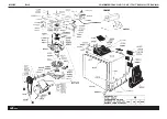
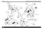
Page 36: ...N 102180 Rev 6 COMBINED FALCOAF 1718 AF1720 IT RACING ITE RACING...
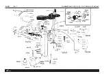
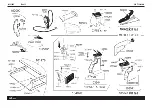
Page 37: ...N 102583 Rev 6 COMBINED FALCOAF 1718 AF1720 IT RACING ITE RACING...
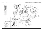
Page 38: ...N 101051 Rev 5 COMBINED FALCOAF 1718 AF1720 IT RACING ITE RACING...
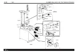
Page 39: ...N 101065 Rev 5 COMBINED FALCOAF 1718 AF1720 IT RACING ITE RACING...
Page 40: ...N 101045 Rev 13 OPTIONAL...
Page 41: ...N 102181 Rev 4 COMBINED FALCOAF 1718 AF1720 IT RACING ITE RACING...
Page 42: ...N 101074 Rev 5 COMBINED FALCOAF 1718 AF1720 IT RACING ITE RACING...
Page 43: ...N 101289 Rev 4 COMBINED FALCOAF 1718 AF1720 IT RACING ITE RACING...
Page 44: ...N 101122 Rev 0 COMBINED FALCOAF 1718 AF1720 IT RACING ITE RACING...
Page 45: ...N 101120 Rev 7 COMBINED FALCOAF 1718 AF1720 IT RACING ITE RACING...
Page 46: ...N 101519 Rev 2 COMBINED FALCOAF 1718 AF1720 IT RACING ITE RACING...
Page 47: ...N 100933 01 Rev 0 COMBINED FALCOAF 1718 AF1720 IT RACING ITE RACING...
Page 48: ...N 100933 02 Rev 0 COMBINED FALCOAF 1718 AF1720 IT RACING ITE RACING...
Page 49: ...N 100933 03 Rev 0 COMBINED FALCOAF 1718 AF1720 IT RACING ITE RACING...
Page 50: ...N 100933 04 Rev 0 COMBINED FALCOAF 1718 AF1720 IT RACING ITE RACING...
Page 51: ...N 101125 01 Rev 0 COMBINED FALCOAF 1718 AF1720 IT RACING ITE RACING...
Page 52: ...N 101125 02 Rev 0 COMBINED FALCOAF 1718 AF1720 IT RACING ITE RACING...
Page 53: ...N 101125 03 Rev 0 COMBINED FALCOAF 1718 AF1720 IT RACING ITE RACING...

