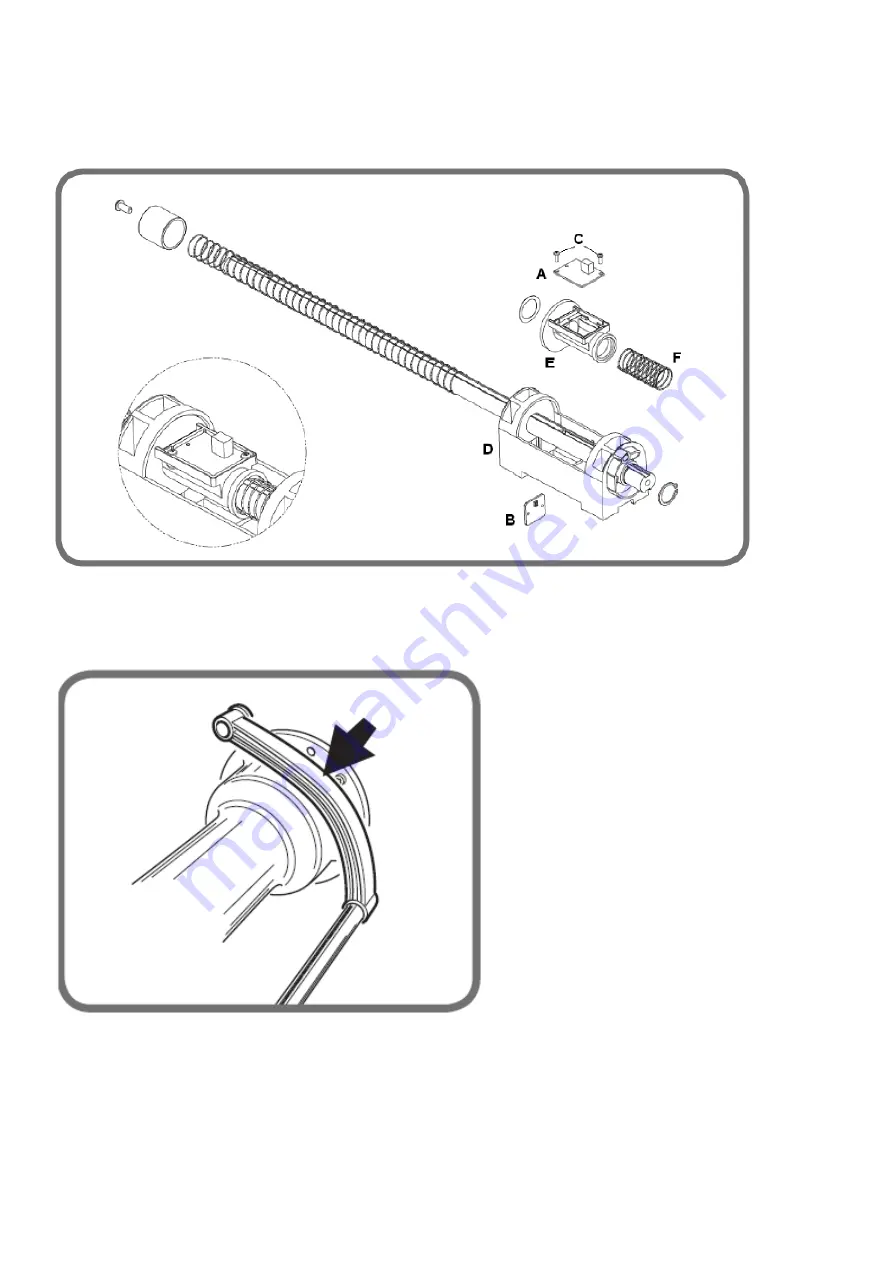
12. INTERNAL AND EXTERNAL SENSOR
(MECHANICAL MEASURING SENSOR OR ULTRASONIC SENSOR)
To view the sensor signals access the service environment;
Fig. 6
12.1 Diameter sensor
Check that the stroke is made up of -110 notches with the lever resting on the bell of the swinging unit see Fig. 7 (maximum error a/- 5
notches in the position indicated).
Fig. 7
If the sensor (B, fig.6) does not read, check:
- the connection flat (L, fig 5);
- that the sensor is correctly assembled in its housing.
If these checks do not rectify the problem, replace the sensor
(B, fig.6) as follows:
- remove the weight tray
- remove the sensor lever;
- disassemble the measuring sensor support (D, Fig. 6), using the 4 fixing screws, from the internal plane;
Summary of Contents for S 64E
Page 43: ...Fig 20 fig 21...
Page 45: ......
Page 46: ...SECOND VERSION OF PNEUMATIC SYSTEM from April 2016...
Page 47: ...THIRD VERSION OF PNEUMATIC SYSTEM from March 2017...
Page 48: ...FOURTH VERSION OF PNEUMATIC SYSTEM...
Page 50: ...PEAL 32F...
Page 51: ......
Page 52: ...MBUGRF 2 LIGHT...
Page 53: ......
Page 54: ...COMIM Cod 4 119446B_EN 05 2018...


