Chapter
6
Operating Instructions
CLV65x Bar Code Scanner
60
©
SICK AG · Division Auto Ident · Germany · All rights reserved
8011980/0000/2009-04-21
Electrical installation
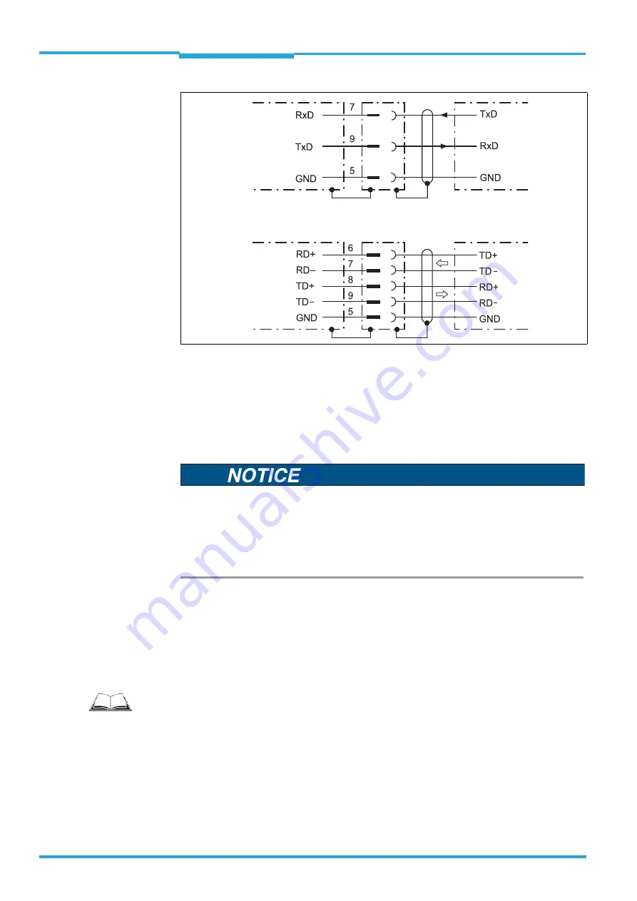
Fig. 6-4:
Wiring the serial host data interfaces (RS-232 or RS-422) on the 15-pole D-Sub-HD plug
Pin assignment for the serial auxiliary data interface on the 15-pole D-Sub-HD plug:
•
RxD = Pin 2
•
TxD = Pin 3
•
GND = Pin 5
1. Connect the bar code scanner's serial interface to the host in accordance with the EMC
regulations using shielded cables.
Adhere to the maximum cable lengths.
2. To prevent interference, do not lay cables parallel to power supply cables and motor
lines over a longer distance, e. g. in cable channels.
CLV
Host
Host
CLV
RS-232
RS-422
Damage to the interface module!
Incorrect wiring of the serial data interfaces can damage electronic components in the bar
code scanner.
Observe information about wiring the serial data interface.
Check the wiring carefully before switching on the bar code scanner.
Important
Terminating the RS-422 data interface
Termination can be performed either in connection module CDB620 or CDM420. See ope-
rating instructions "Connection module CDB620" or "Connection module CDM420".


