Chapter
4
Operating Instructions
CLV 42x bar code scanner
4-8
©
SICK AG · Division Auto Ident · Germany · All rights reserved
8 009 981/O078/16-08-2004
Installation
2.
Connect the PC to the terminal interface of the CLV. For this purpose, connect a 3-core
RS 232 data cable to the internal 9-pin "Aux" plug of the module (
see
).
3.
Start Windows and "CLV Setup" on your PC (
see
Chapter 10.4.3 Starting "CLV Setup",
).
Activating “Percentage Evaluation“ mode
4.
From the V
IEW
menu, choose P
ERCENTAGE
EVALUATION
.
5.
The dialog window for choosing the distance configuration is then displayed.
6.
Confirm the dialog window with "OK".
The Terminal Emulator is launched and displays the reading result continuously (s
ee
Chapter 6.5.2 Percentage evaluation, Page 6-17
).
Monitor the
reading quality
(%) during each of the subsequent steps!
Performing fine adjustment
7.
Align the CLV in such a way that the angle between the scan line and the bars on the
bar code CLV is almost 90
°
.
8.
To prevent interfering reflections, tilt the CLV away from the vertical axis so that the light
strikes the bar code at an angle of approx. 105
°
(line scanner) (
9.
If necessary, position the center of the scan line exactly on the bar code (
see
Chapter 4.3.3 Auxiliary functions for adjustment, Page 4-8
10. Move objects carrying bar codes into the CLV reading field manually under realistic
conditions and check the reading result. If the objects are aligned randomly, or if the bar
code is located at different positions (angles), ensure that the limit values of the
permissible reading angles are not exceeded.
11. Adjust the CLV in such a way that the good read rate is between
70 and 100 %
.
12. Tighten the screws on the CLV.
The CLV is aligned with the bar code.
4.3.3
Auxiliary functions for adjustment
Adjusting mode
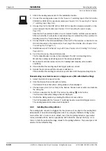
The "adjusting mode" helps you to position the
center
of the scan line on the object. To do
so, the CLV masks out one half of the scan line from the center (code position CP = 50 to
CP = 100).
shows the resulting appearance of the scan line with the line scanner.
Fig. 4-9:
Line scanner: appearance of the scan line in the "adjusting mode" operating mode
CP = 100
CP = 50
CP = 0
"Adjusting mode"
Scan line
masked out
area


