


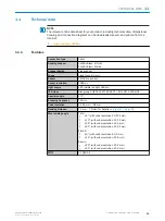
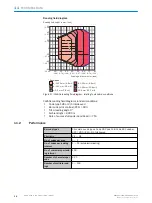
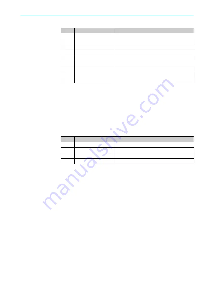
Table 7: Pin assignment on 9-pin D-Sub-HD male cable connector
Pin
Signal
Function
1
In1
Digital switching input
2
RxD (HOST)
HOST interface (receiver)
3
TxD (HOST)
HOST interface (sender)
4
Out1
Digital switching output 1
5
GND
Ground
6
Out2
Digital switching output 2
7
RxD (AUX)
AUX interface (receiver)
8
TxD (AUX)
AUX interface (sender)
9
+5V
Supply voltage
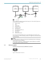
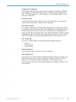
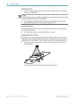
Connection of devices with cable and USB male connector
Devices with cable and USB-a_connector can be operated in the Keyboard wedge (HID),
Virtual COM port (CDC) and SOPAS (vendor-specific) operating modes. Switching over is
not necessary since this happens automatically via USB Composite.
Properties of different operating modes:
•
USB-HID (Human Interface Device)
: Keyboard connector, scanner is operated as a
generic USB keyboard.
•
Virtual COM Port
: Scanner is operated via an emulator as a serial RS-232 device.
•
SOPAS-USB
: Alternative to the virtual COM port
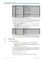
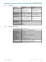
Table 8: Pin assignment on 4-pin USB A male cable connector
Pin
Signal
Function
1
+5V
Supply voltage
2
Data-
Data input
3
Data+
Data output
4
GND
Ground
Before connecting for the first time, install the USB COM port driver (available at
). A standard virtual COM port driver is integrated from Windows
10. The SOPAS ET software must be installed on the host computer to use SOPAS USB.
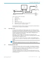
6.4
Wiring interfaces
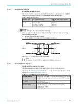
6.4.1
Connecting the supply voltage
The device must be connected to a power supply unit with the following properties:
•
Supply voltage 5 V DC ± 10% (stabilized safety extra-low voltage SELV (EN
60950-1) and LPS (IEC 60950-1) or ES-1 and PS2 (EN 62368-1) as per currently
valid standards)
•
Voltage source with at least 1.5 W power
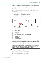
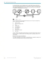
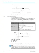
When configuring the voltage supply, the switch-on current of the device must be taken
into consideration. The initial power consumption depends on the input capacitors of
the device. The input capacitor is about 50 μF for the RS232 variant. If, for example, 10
devices with a voltage supply are used, that means:
Pmax = 10 * 1.5 W = 15 W
Sum of capacitators = 10 * 50 μF = 500 μF
The voltage supply should be able to process 500 μF load for commissioning.
6
ELECTRICAL INSTALLATION
24
O P E R A T I N G I N S T R U C T I O N S | CLV60x
8021817/10Y9/2018-09-14 | SICK
Subject to change without notice