6.4.2
Wiring the data interface
Wiring the serial data interface
The maximum data transmission rate for the serial interface depends on the length of
cable and on the type of interface. The following recommendations apply:
Table 9: Data transmission rates
Interface type
Data transmission rate
Distance to the target computer
(host)
RS-232
Up to 19.2 kBd
38.4 kBd ... 57.6 kBd
115.2 kBd … 500 kBd
Max. 10 m
Max. 3 m
Max. 2 m
NOTICE
Risk of damage to the internal interface modules!
If the serial data interfaces are wired incorrectly, then electronic components in the
device could get damaged.
■
Observe the information on wiring.
■
Carefully check the wiring prior to switching on the device.
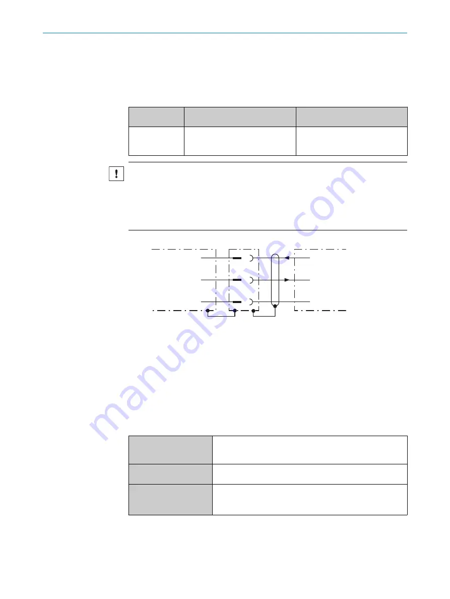
RS-232
!
"
§
Device
1
Host
TxD
RxD
GND
RxD
TxD
GND
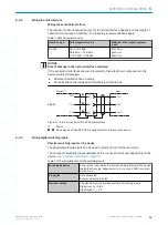
Figure 12: Internal circuitry for RS-232 data interface
1
Device
!
...
§
Pin assignment: See RS-232 pin assignment for the respective device
6.4.3
Wiring digital switching inputs
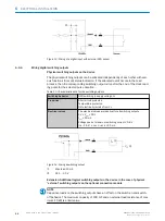
Physical switching inputs on the device
The physical switching inputs can be used to start and/or end the read cycle.
The number of switching inputs available at the connections will vary depending on the
device,
see "Interface description", page 23
Table 10: Characteristic data for the switching inputs
Switching behavior
Power at the input starts the internal reading interval of the device
[default: active high, debounce: min. 1 ms, max. 10000 ms, stan‐
dard 10 ms]
Properties
Opto-decoupled
Reverse polarity protected
Electrical values
The electrical values are identical for all switching inputs.
Digital low: V
in
< 0.8 V
Digital high: V
in
> 3 V
ELECTRICAL INSTALLATION
6
8021817/10Y9/2018-09-14 | SICK
O P E R A T I N G I N S T R U C T I O N S | CLV60x
25
Subject to change without notice


