background image

2

Safety information

2.1

Intended use

The CLV60x bar code scanner is an intelligent, opto-electronic ID sensor and is used for
automatic, fixed identification and decoding of bar codes on moving or stationary
objects. The data content of the decoded bar codes is transmitted via the device to a
higher-level control (PLC) or an industrial computer for coordinating processing.

NOTE

The bar codes to be read must comply at least with quality level C in accordance with
ISO/IEC 15416.

The product variants with connecting cable and USB plug are not designed for rough
industrial environments with strong electromagnetic interference. During installation,
make sure that no sources of interference are in the direct vicinity of the product. Use
the USB devices in offices or in applications with similar ambient conditions (e.g.
libraries or laboratories).

SICK AG assumes no liability for losses or damage arising from the use of the product,
either directly or indirectly. This applies in particular to use of the product that does not
conform to its intended purpose and is not described in this documentation.

2.2

Improper use

Any use outside of the stated areas, in particular use outside of the technical specifica‐
tions and the requirements for intended use, will be deemed to be incorrect use.

The device does not constitute a safety component in accordance with the respec‐
tive applicable safety standards for machines.

The device must not be used in explosion-hazardous areas, in corrosive environ‐
ments or under extreme environmental conditions.

Any use of accessories not specifically approved by SICK AG is at your own risk.

WARNING
Danger due to improper use!

Any improper use can result in dangerous situations.
Therefore, observe the following information:

Device should be used only in accordance with its intended use.

All information in these operating instructions must be strictly observed.

2.3

IP technology

NOTE

SICK uses standard IP technology in its products. The emphasis is placed on availability
of products and services.
SICK always assumes the following prerequisites:

The customer ensures the integrity and confidentiality of the data and rights
affected by its own use of the aforementioned products.

In all cases, the customer implements the appropriate security measures, such


as

network separation, firewalls, virus protection, and patch management.

SAFETY INFORMATION 

2

8021817/10Y9/2018-09-14 | SICK

O P E R A T I N G   I N S T R U C T I O N S | CLV60x

7

Subject to change without notice

Summary of Contents for CLV60 series

Page 1: ...O P E R A T I N G I N S T R U C T I O N S CLV60x Bar code scanners ...

Page 2: ...ible within the limits of the legal determination of Copyright Law Any modifica tion abridgment or translation of this document is prohibited without the express writ ten permission of SICK AG The trademarks stated in this document are the property of their respective owner SICK AG All rights reserved Original document This document is an original document of SICK AG 2 O P E R A T I N G I N S T R ...

Page 3: ...l 13 3 7 Reading operation mode 13 4 Transport and storage 15 4 1 Transport 15 4 2 Unpacking 15 4 3 Transport inspection 15 4 4 Storage 15 5 Mounting 16 5 1 Overview of mounting procedure 16 5 2 Mounting instructions 16 5 3 Mounting location 16 5 3 1 Basic alignment of the scan line to the bar code 16 5 3 2 Reading distance to the bar code and aperture angle α 17 5 3 3 Angle alignment of the devic...

Page 4: ...nance 31 9 2 Cleaning 31 10 Troubleshooting 33 10 1 Overview of possible errors and faults 33 10 2 Detailed fault analysis 33 10 2 1 LEDs on the device 33 10 2 2 System information 33 10 3 Status log 33 10 3 1 Displaying the status log 34 10 4 Repairs 34 10 5 Returns 34 10 6 Disposal 34 11 Technical data 35 11 1 Features 35 11 2 Performance 36 11 3 Interfaces 37 11 4 Mechanics electronics 37 11 5 ...

Page 5: ... operating the machine or system in which the device is integrated For information about this refer to the operat ing instructions of the specific machine 1 2 Explanation of symbols Warnings and important information in this document are labeled with symbols The warnings are introduced by signal words that indicate the extent of the danger These warnings must be observed at all times and care must...

Page 6: ... and specification diagrams EU declaration of conformity for the product family Dimensional drawings and 3D CAD dimension models in various electronic for mats These operating instructions available in English and German and in other lan guages if necessary Other publications related to the devices described here Publications dealing with accessories 1 ABOUT THIS DOCUMENT 6 O P E R A T I N G I N S...

Page 7: ...ted areas in particular use outside of the technical specifica tions and the requirements for intended use will be deemed to be incorrect use The device does not constitute a safety component in accordance with the respec tive applicable safety standards for machines The device must not be used in explosion hazardous areas in corrosive environ ments or under extreme environmental conditions Any us...

Page 8: ...ARNING Risk of injury due to insufficient training Improper handling of the device may result in considerable personal injury and material damage All work must only ever be carried out by the stipulated persons The operating instructions state the following qualification requirements for the various areas of work Instructed personnel have been briefed by the operator about the tasks assigned to th...

Page 9: ...oid dan gerous situations The product is fitted with LEDs of the risk group 0 The accessible radiation from these LEDs does not pose a danger to the eyes or skin WARNING Electrical voltage Electrical voltage can cause severe injury or death Work on electrical systems must only be performed by qualified electricians The power supply must be disconnected when attaching and detaching electrical conne...

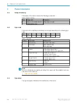
Page 10: ...601 Standard range 602 Long range 3 Version 0 Reading window at front 1 Reading window on side angle 103 4 Connection type A With open cable end U USB A male connector D D SUB male connector 9 pin 5 Length of cable 1 Cable approx 1 5 m 2 Cable approx 2 0 m 6 Host interface 0 RS 232 1 USB 7 Supply voltage 0 DC 5 V 10 NOTE Not all combinations are possible according to the type code The available de...

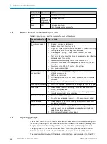
Page 11: ... Err UserDef1 Figure 2 Status indicators 1 Status LED Table 4 Display behavior of the LED Color of LED Status Status OFF Device without supply voltage After switching on Parameter download for the device Blue ON After switching on or after firmware download Self test successful device ready for operation Green Lights up briefly Reading successful Good Read Red Lights up briefly Reading unsuccessfu...

Page 12: ... Read operation modes Start stop operation one bar code bearing object per read cycle Read cycle Pulse sources for start Switching inputs data interface com mand auto pulse free Pulse sources for stop Read cycle source switching inputs data interface command timer condition Bar code evaluation All current 1D bar code types No of codes per reading interval 1 15 auto discriminating Data processing I...

Page 13: ...or the read process Alternatively a command triggers the read process via a data interface or the SICK SENSOR network In auto pulse mode the device internally generates the reading interval itself with an adjustable clock ratio The read cycle can be ended in several ways For example external triggering by the read cycle source or a command or internally by a timer or a evaluation condition to be f...

Page 14: ...igger 1 Start reading 3 Reading field 4 Start Stop mode 1 Figure 4 Start stop operating mode of the device in stand alone operation 1 Start stop operation 2 Trigger 2 Stop reading 3 Trigger 1 Start reading 4 Reading field 5 Data output NOTE The SOPAS ET configuration software can be used to configure the reading operation mode 3 PRODUCT DESCRIPTION 14 O P E R A T I N G I N S T R U C T I O N S CLV6...

Page 15: ...amage that is visible externally proceed as follows Do not accept the delivery or only do so conditionally Note the scope of damage on the transport documents or on the transport com pany s delivery note File a complaint NOTE Complaints regarding defects should be filed as soon as these are detected Damage claims are only valid before the applicable complaint deadlines 4 4 Storage Store the device...

Page 16: ...ice to rapid changes in tempera ture Protect the device from direct sunlight The device must only be mounted using the pairs of blind tapped holes provided for this purpose Shock and vibration free mounting Equipment required NOTE The screws are for mounting the device on mounting equipment bracket supplied by the user Screw length is dependent on the mounting base wall thickness of the bracket To...

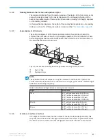
Page 17: ...ngle occurring between scanning line and bar code 1 Depth of field 2 Reading distance NOTE The specified maximum values can only be achieved if conditions are optimal The actual maximum depends on the module width code type print contrast ambient light distance and scanning frequency Table 6 Permitted read angle between scanning line and bar code Angle Limit value Tilt α 5 with code resolution 0 1...

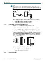
Page 18: ...hem The reading angle starting from the reading window at which the device detects the bar code center on the red scanning line of the deflected scanning beam can be output as an RA reading angle value By determining the RA value identical bar codes code type code length and data con tent can be separated and the bar code data assigned based on their position on the object 1 RA corresponds to abou...

Page 19: ...ide with the reading window is aligned as near as possible to parallel to the bar code surface During reading note the reading angle that occurs see Angle alignment of the device page 17 If the position of the bar code within the scanning line is relevant for the eval uation bear in mind the count direction of the code position see Counting direction of the reading angle and the code angle page 18...

Page 20: ...design correctly and completely To avoid interference e g from switching power supplies motors clocked drives and contactors always use cables and layouts that are suitable for EMC Do not lay cables over long distances in parallel with power supply cables and motor cables in cable channels 6 2 Prerequisites for safe operation of the device WARNING Risk of injury and damage caused by electrical cur...

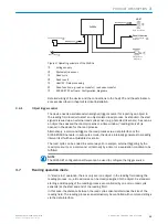
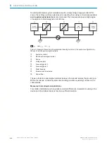
Page 21: ...r 2 Device 3 Voltage supply 4 Grounding point 2 5 Closed current loop with equalizing currents via cable shield 6 Ground potential difference 7 Grounding point 1 8 Metal housing 9 Shielded electrical cable If these conditions are not fulfilled equipotential bonding currents can flow along the cable shielding between the devices due to differing ground potentials and cause the hazards specified Thi...

Page 22: ... electro optical signal isolators 1 System controller 2 Electro optical signal isolator 3 Device 4 Voltage supply 5 Grounding point 2 6 Grounding point 1 7 Metal housing 8 Shielded electrical cable 9 Optical fiber The use of electro optical signal isolators between the islands isolates the ground loop Within the islands a stable equipotential bonding prevents equalizing currents on the cable shiel...

Page 23: ...l ground loops are effec tively prevented As a result equalizing currents can no longer flow via the cable shields and metal housing NOTICE The voltage supply for the device and the connected peripheral devices must also guar antee the required level of insulation Under certain circumstances a tangible potential can develop between the insulated metal housings and the local ground potential 6 3 In...

Page 24: ...ta input 3 Data Data output 4 GND Ground Before connecting for the first time install the USB COM port driver available at www sick com CLV60x A standard virtual COM port driver is integrated from Windows 10 The SOPAS ET software must be installed on the host computer to use SOPAS USB 6 4 Wiring interfaces 6 4 1 Connecting the supply voltage The device must be connected to a power supply unit with...

Page 25: ...Internal circuitry for RS 232 data interface 1 Device Pin assignment See RS 232 pin assignment for the respective device 6 4 3 Wiring digital switching inputs Physical switching inputs on the device The physical switching inputs can be used to start and or end the read cycle The number of switching inputs available at the connections will vary depending on the device see Interface description page...

Page 26: ...Temperature protected Not electrically isolated from VS Electrical values The electrical values are identical for all switching outputs 5 V Vout 30 V Iout 50 mA Voltage peak at maximum switching current 0 8 V US 1 5 V Ua Us at Ia 50 mA Figure 14 Wiring a switching output 1 Max load 50 mA 2 DC 5 30 V Extension Additional logical switching outputs in the device in the case of physical external switc...

Page 27: ...g functions use a high resistance digital voltmeter and wire the switching outputs with a load This prevents the display of incorrect voltage values output states ELECTRICAL INSTALLATION 6 8021817 10Y9 2018 09 14 SICK O P E R A T I N G I N S T R U C T I O N S CLV60x 27 Subject to change without notice ...
Page 28: ...e is used to create an application specific parameter set which can be loaded per manently into the device and saved and archived as a project file SOPAS file with con figuration data on the PC ROM PROM RAM RAM Database Hard drive Bar code scanner PC with SOPAS ET configuration software Parameter set in the working memory of the bar code scanner Permanently saved parameter set Saved project file s...

Page 29: ...y emits read results every 2 s via the AUX interface together with the read diagnostic data A timer starts when percentage evaluation is called If a manual abort is not carried out the device automatically returns to read mode after 5 min Code configuration In the factory default setting the device decodes the following code types Code 39 2 5 Interleaved Code 128 family Scanning frequency The scan...

Page 30: ...n which the operator interface of the configuration software is also based These are also for the triggering of device functions e g reading Docu ments on the command strings can be obtained from SICK on request Profile programming by reading a set of printed configuration bar codes Can be created via SOPAS ET The SOPAS ET configuration software is used for device diagnostics in case of a fault In...

Page 31: ...leaning agents Never use sharp objects for cleaning Cleaning the reading window At regular intervals check the reading window and the housing of the device for accu mulated dirt This is especially relevant in harsh operating environments dust abra sion damp fingerprints etc The reading window lens must be kept clean and dry during operation NOTICE Damage to the reading window Reduced analysis perf...

Page 32: ...evice the housing sur face must be kept clean b Clear the build up of dust on the housing with a soft brush Cleaning other optical surfaces Depending on how the reading station is equipped additional local sensors may have other surfaces with an optical effect installed e g photoelectric sensor for an external reading pulse Contamination on these sensors can result in faulty switching behavior b T...

Page 33: ...ce LEDs on the sensor housing see Sta tus indicators page 11 include Operational readiness Ready Reading result status Good Read or No Read Hardware fault Firmware download status Connection status of the device The LED display can indicate possible errors or faults Further information on this can be found in the System Information section 10 2 2 System information The device outputs faults in dif...

Page 34: ...ed pack aging NOTE To enable efficient processing and allow us to determine the cause quickly please include the following when making a return Details of the contact person Description of the application Description of the fault that occurred 10 6 Disposal Any device which can no longer be used must be disposed of in an environmentally friendly manner in accordance with the applicable country spe...

Page 35: ...ht 626 nm LED class Risk group 0 IEC 621471 2006 07 EN 62471 2008 09 Aperture angle 71 Scanning frequency 750 Hz Code resolution 0 125 mm 0 5 mm Reading distance 15 mm 70 mm for details see figure 17 page 36 Max reading angle Tilt α 5 with code resolution 0 125 mm 10 with code resolution 0 15 mm 15 with code resolution 0 2 mm 25 with code resolution 0 35 mm Pitch β 6 with code resolution 0 2 mm 15...

Page 36: ... standard conditions Code type 128 or 2 5 Interleaved Bar code print contrast PCS 90 Tilt α reading angle 0 Ambient light 2 000 lx Rate of successful reads Good Read 75 11 2 Performance Bar code types All common code types Code 39 Code 128 Code 93 Codabar UPC GTIN EAN 2 5 Interleaved Print ratio 2 1 3 1 No of codes per scan 1 1 No of codes per reading interval 1 15 auto discriminating No of charac...

Page 37: ...ustic indicators Beeper can be switched off or allocated a function for indicating events Configuration software SOPAS ET 11 4 Mechanics electronics Table 14 Technical data for mechanics electronics Electrical connection CLV60x xDxxx 1 x 9 pin D Sub male connector CLV60x xUxxx 1 x USB A male connector Supply voltage 5 V DC 10 Power consumption 1 W typical Housing Zinc die cast Housing color Light ...

Page 38: ... 5 4 0 21 2 Figure 18 Dimensional drawing CLV60x 0xxxx dimensions in mm 1 Mounting thread M3 x 5 mm 2 Optical axis reading window 3 Reading distance reference point 4 Reading field axis center 5 Reading field 6 Status LED 7 Reading window 8 Type label 9 Connecting cable 11 TECHNICAL DATA 38 O P E R A T I N G I N S T R U C T I O N S CLV60x 8021817 10Y9 2018 09 14 SICK Subject to change without noti...

Page 39: ... field axis center 5 Reading field 6 Status LED 7 Reading window 8 Type label 9 Connecting cable 11 5 Ambient data Electromagnetic compati bility EM EN 61000 6 3 2007 01 EN 61000 6 2 2005 02 Vibration resistance EN 60068 2 6 2008 02 Shock resistance EN 60068 2 27 2009 05 Ambient operating temper ature 0 C 50 C Storage temperature 20 C 70 C Permissible relative humidity 90 non condensing Ambient li...

Page 40: ...Bar code print contrast PCS 60 11 TECHNICAL DATA 40 O P E R A T I N G I N S T R U C T I O N S CLV60x 8021817 10Y9 2018 09 14 SICK Subject to change without notice ...

Page 41: ...pen source software This software is licensed by the rights holders using the following licenses among others the free licenses GNU General Public License GPL Version2 GPL Version3 and GNU Lesser General Public License LGPL the MIT license zLib license and the licenses derived from the BSD license This program is provided for general use but WITHOUT ANY WARRANTY OF ANY KIND This warranty disclaime...

Page 42: ...xico Phone 52 472 748 9451 E Mail mario garcia sick com Netherlands Phone 31 0 30 229 25 44 E Mail info sick nl New Zealand Phone 64 9 415 0459 0800 222 278 tollfree E Mail sales sick co nz Norway Phone 47 67 81 50 00 E Mail sick sick no Poland Phone 48 22 539 41 00 E Mail info sick pl Romania Phone 40 356 17 11 20 E Mail office sick ro Russia Phone 7 495 283 09 90 E Mail info sick ru Singapore Ph...

Reviews: