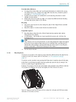
Focus
position
Focus position
2
Reading distance
3
Reading distance
3
DC = distance configuration
4
DC8
DC7
DC6
DC5
DC4
DC
3
DC
2
DC
1
Reading
field
height
1
2
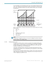
Figure 10: Focus switching - dividing the total read area into distance configurations
1
Reading field height
2
Focus position
3
Reading distance
4
Distance configuration
The switching of the focus is carried out by the changing object distance (e.g. during
reading from the top: object height detection).
Trigger sources for switching are:
–
Signal at switching input e.g. “sensor 2” for the max. 2-stage switching
–
Command to the host interface or the integrated timer (e.g. for search run) for the
max. 8-level switching
–
Oscillating mirror dead centers of the double-sided deflection for line scanner with
oscillating mirror
The distance configurations are assigned to the switching order via a programmable
assignment table.
NOTE
The SOPAS-ET configuration software can be used to configure the focus position:
•
Project tree, CLV6xx, parameters, read configuration
•
Project tree, CLV6xx, parameters, read configuration, oscillating mirror
•
Project tree, CLV6xx, parameters, read configuration, focus control
3.2.3.4
Oscillating mirror control
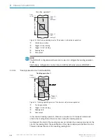
In the case of a line scanner with oscillating mirror, the position of the scan line is influ‐
enced by the configuration of the oscillating mirror.
In addition to the “Park” (fixed, adjustable position of the scan line) or the continuous
oscillation (irrespective of the read cycle), optimized function processes related to the
read cycle are also possible in the controlled operation of oscillating mirror:
–
N times vibrations at an adjustable start position within the read cycle
–
One-Shot: single deflection (approach and return) per read cycle from an
adjustable start position
3
PRODUCT DESCRIPTION
22
O P E R A T I N G I N S T R U C T I O N S | CLV63x, CLV64x, CLV65x
8019588/129Z/2019-02-07 | SICK
Subject to change without notice


