Data
output
Trigger 2:
Stop
Trigger 1:
Start
R
e
a
d
ing
f
ie
ld
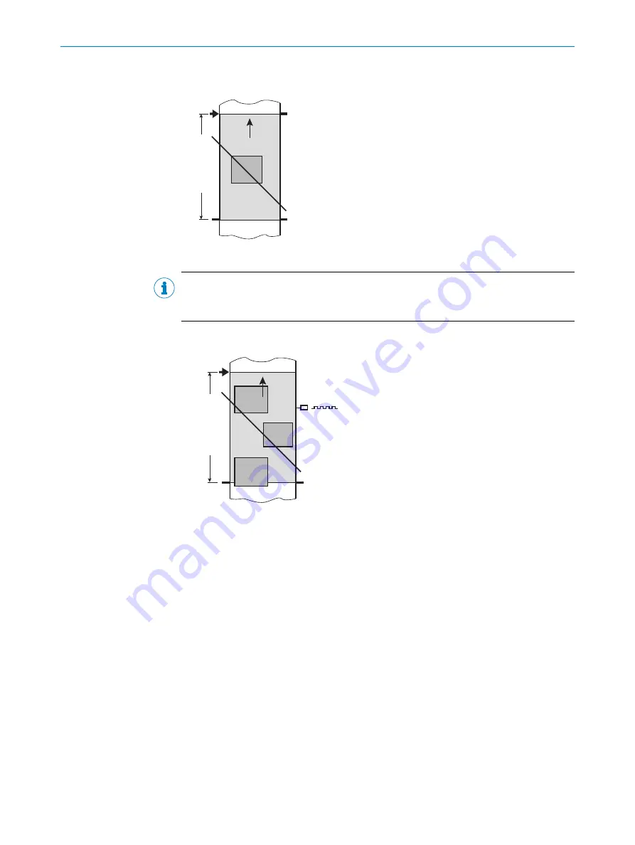
Start/stop operation
Figure 9: Start/stop operating mode of the device in stand-alone operation
NOTE
The SOPAS ET configuration software can be used to configure the reading operation
mode.
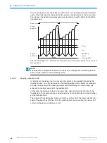
Tracking operation
Trigger 1:
Start
R
e
a
d
ing
f
ie
ld
Data
output
Figure 10: Tracking operating mode of the device in stand-alone operation
In the internal tracking operation, there are a maximum of 10 objects behind each
other in the reading field at the same time during the reading process.
As standard, the start of the reading process is controlled by a read cycle sensor at the
start of the reading field. The specification of the object release point defines the end.
This also defines the size of the resulting reading field.
In order to be able to track the transport of the objects in the reading field, a regular
cycle is required. This is generated by an external incremental encoder, which con‐
stantly provides at least one pulse per 1 mm movement in the conveyor direction. This
provides a clear temporal representation in the device of the route between the read
cycle sensor and object release point.
Jittering when the conveyor technology is starting up or in the event of slowing down
when there is a high load with lots of objects to convey is therefore also recorded. An
internal pulse generator in the device alternatively allows for operation at a conveyor
speed that is always constant.
A gap of at least 50 mm is necessary for clear separation of successive objects.
The issuing of the read result for an object is carried out after the rear edge of the
object passes the object release point. The reading process can alternatively be started
with a command string via the data interface.
PRODUCT DESCRIPTION
3
8014396/ZMG8/2017-07-04 | SICK
O P E R A T I N G I N S T R U C T I O N S | CLV69x
19
Subject to change without notice


