8
Operation
8.1
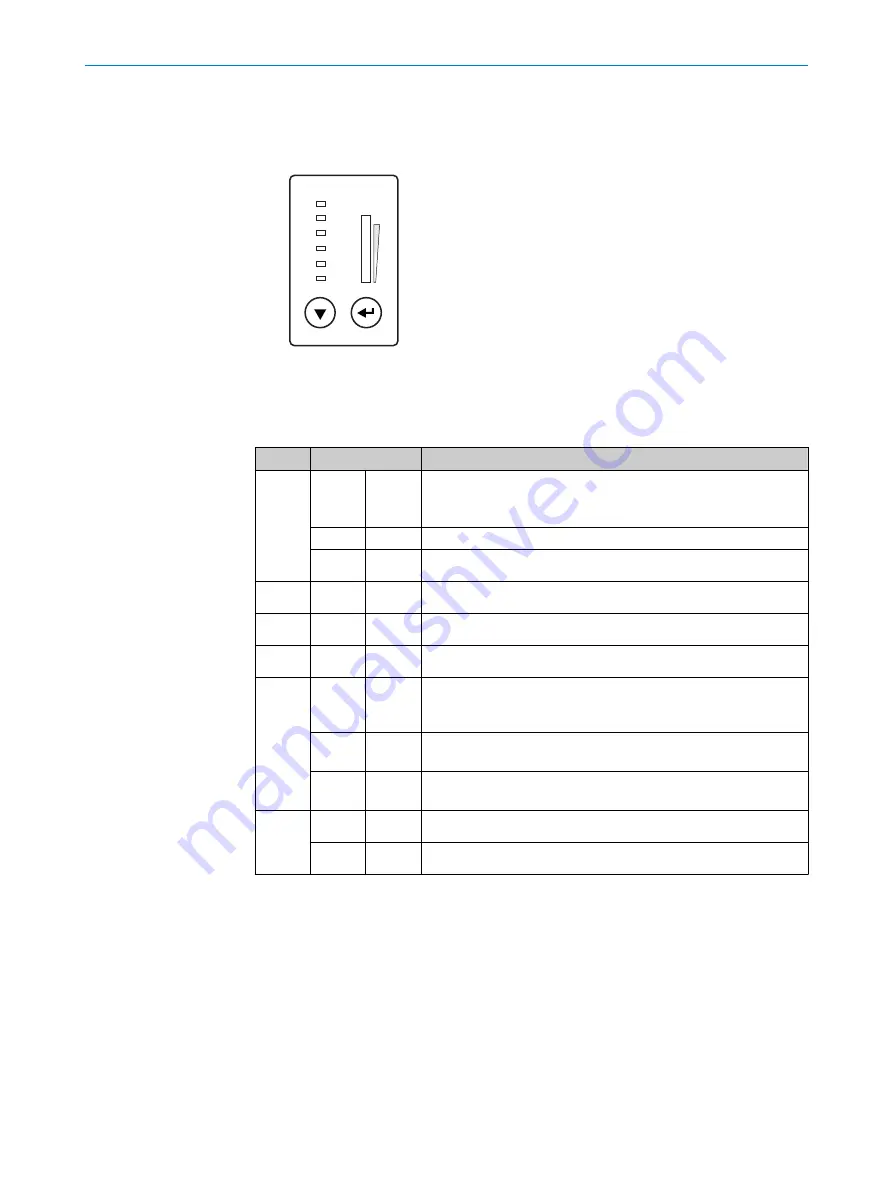
Optical displays and control elements
Ready
Result
Laser
Data
CAN
LNK TX
Read Diagn
Teach-in
Auto-Setup
Adjusting
User-defined
100
[%]
1
2
Figure 80: LED status indicators, bar graph and function buttons
1
Arrow pushbutton
2
Return pushbutton
Table 10: Illumination behavior of the LED status display
Display LED
Status
Ready
O
green
Lights up constantly after switching on and completion of success‐
ful self-test
The device is ready for reading
Goes out when downloading or uploading configuration data
O
red
Hardware fault
Result
O
green
Successful reading
Laser
O
green
Laser on
Data
O
green
Data output via host interface
CAN
Ö
green
Data transmission via CAN interface, status of the internal termi‐
nation of the cloning plug: all existing terminations are not active,
or not available (depending on the plug)
Ö
blue
Data transmission via CAN interface, status of the internal termi‐
nation of the cloning plug: all existing terminations are active
Ö
purple
Data transmission via CAN interface, status of the internal termi‐
nation of the cloning plug: not all existing terminations are active
LNK TX
O
green
Physical Ethernet connection
Ö
green
Data traffic via Ethernet
O
= illuminated,
Ö
= flashing
Operating button and status displays on the second display level
The two pushbuttons
1
and
2
are used to call up device functions manually without
using a PC. The second display level of the LEDs signals the selectable functions. Cur‐
rently, “Read Diagn” (percentage evaluation) and “Adjusting” (adjusting tool) are availa‐
ble.
1.
Press the return key for approx. 2 seconds. The device switches to operating mode
of the pushbutton. “Ready” LED now lights up blue.
2.
Press arrow key repeatedly to select the desired function (LED lights up blue).
8
OPERATION
88
O P E R A T I N G I N S T R U C T I O N S | CLV69x
8014396/ZMG8/2017-07-04 | SICK
Subject to change without notice


