3
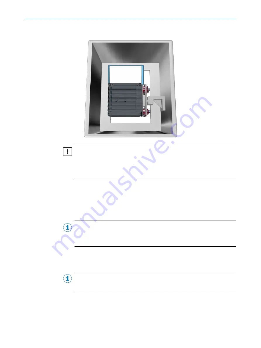
Mounting of oscillating mirror scanner (horizontal reading line), ball joint bracket
and mounting bracket with integrated vibration/shock attenuation
NOTICE
Risk of damaging the device
An incorrect installation position restricts the attenuation effect or amplifies strains that
occur.
•
Only carry out one of the three mounting variants listed.
5.7
Mounting of external components
5.7.1
Mounting the connection module
If the device activation is carried out via a connection module, then this must be
mounted near to the device.
NOTE
If the PC with the configuration software SOPAS ET accesses the AUX interface
(RS-232; 57.6 kBd) of the device via the connection module, then the connection mod‐
ule must be installed no more than a 3 m length of cable from the device.
1.
Mount the connection module in the vicinity of the device.
2.
Mount the connection module in such a way that the open module can be
accessed at all times.
NOTE
Detailed information on mounting and electrical installation can be found in the operat‐
ing instructions for the connection module.
5.7.2
Mount external read cycle sensor
If the device is triggered via an external read cycle sensor (photoelectric retro-reflective
sensor), then the sensor must be mounted in the vicinity of the device.
5
MOUNTING
30
O P E R A T I N G I N S T R U C T I O N S | CLV69x
8014396/ZMG8/2017-07-04 | SICK
Subject to change without notice


