53
8011952/YWL2/3-0/2016-08| SICK
O P E R A T I N G I N S T R U C T I O N S | DUSTHUNTER C200
Subject to change without notice
ASSEMBLY AND INSTALLATION
3
3.3.7
Fitting the interface and I/O module (option)
Plug Interface modules and module carriers for I/O modules onto the hat rail in the MCU
(
see “Component layout in the MCU (without purge air supply, with options)”, page 47
) and
connect to the associated connection on the processor board with the line with plug con-
nector (
see “MCU processor board connections”, page 48
). Then plug the I/O modules on
the module carriers.
Connect the Interface modules using the customer provided network line to the local
network. Use the terminals on the module carrier to connect I/O modules.
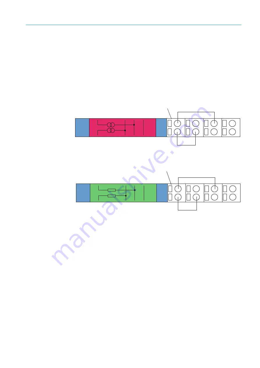
Terminal assignment of AO module
Fig. 31: Terminal assignment of analog output module
Terminal assignment of AI module
Fig. 32: Terminal assignment of analog input module
+
1
AO1
+
2
AO
2
Shield
11
12
13
14
21
22
23
24
AO 1
+ -
AO 2
+ -
Module carrier
+ -
+
1
AI1
11
12
13
14
21
22
23
24
+
2
AI
2
Shield
AI 1
AI 2
+ -
Module carrier


