60
EuroFID · Operating Instructions · 8011094 V2.3 · © SICK AG
Installation of the Operating Unit
6.3
Signal connections
6.3.1
Overview of signal connections
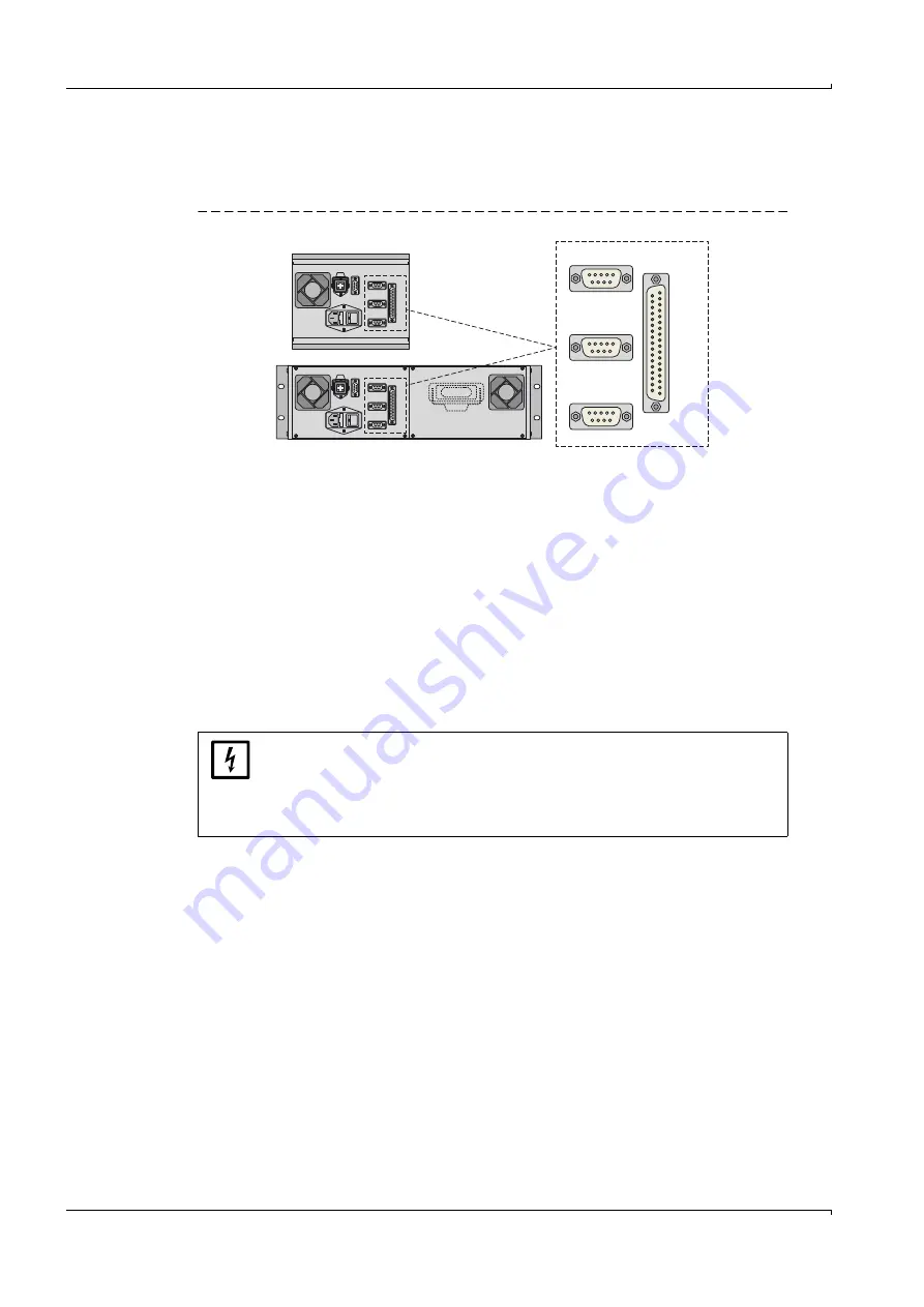
Fig. 19
Operating unit: Plug connector for signal connections
Interfaces
●
“Printer” is a RS232 interface for connecting a printer (
) or a PC (via the
serial int the terminal program; e.g. for transferring measured values and
status messages).
●
“System” and “RS 232C” are interfaces for factory use and servicing.
Measured values and signals
The 37-pole D-SUB plug connector “Analog and digital I/O” provides the electronic signal
outputs and inputs of the EuroFID:
●
Measured value outputs (
●
Analog inputs (
)
●
Control inputs for calibration control (
●
Switching outputs for alarms and status (
)
System
Printer
Drucker
RS 232 C
Analog and Digital I/O
Analog
e
und digitlale
Ein-/A
usgabe
NOTICE:
Before signal connections are established (also with plug connections):
Disconnect the EuroFID and any connected devices from the mains
electrical supply (switch off).
Otherwise the internal electronics could be damaged.
Summary of Contents for EuroFID
Page 10: ...Contents 10 EuroFID Operating Instructions 8011094 V2 3 SICK AG ...
Page 18: ...18 EuroFID Operating Instructions 8011094 V2 3 SICK AG Important Information ...
Page 80: ...80 EuroFID Operating Instructions 8011094 V2 3 SICK AG Start up ...
Page 88: ...88 EuroFID Operating Instructions 8011094 V2 3 SICK AG Operation General ...
Page 100: ...100 EuroFID Operating Instructions 8011094 V2 3 SICK AG Main Menu Functions ...
Page 144: ...144 EuroFID Operating Instructions 8011094 V2 3 SICK AG Maintenance Sub menu Functions ...
Page 154: ...154 EuroFID Operating Instructions 8011094 V2 3 SICK AG Calibration ...
Page 158: ...158 EuroFID Operating Instructions 8011094 V2 3 SICK AG Shutdown ...
Page 182: ...182 EuroFID Operating Instructions 8011094 V2 3 SICK AG Clearing Malfunctions ...


