41
8008250/1F7Y/V4-0/2022-06 | SICK
O P E R A T I N G I N S T R U C T I O N S | GM901
Subject to change without notice
COMMISSIONING
7
7.2.4
Zero adjust
Creating the zero path
▸
Have the assembly bracket for zero adjust ready.
▸
Remove the purge air fixtures from the sender and receiver, and secure them on the
assembly bracket (available as an option).
▸
Attach the holder for the CO cell, e.g., on the sender; but do
not
use a cell filled with CO
when a sensitivity test is also planned.
▸
Adjust the assembly bracket to the flange - flange (cell holder) measure minus 85 mm of
the duct measuring distance as shown in
.
▸
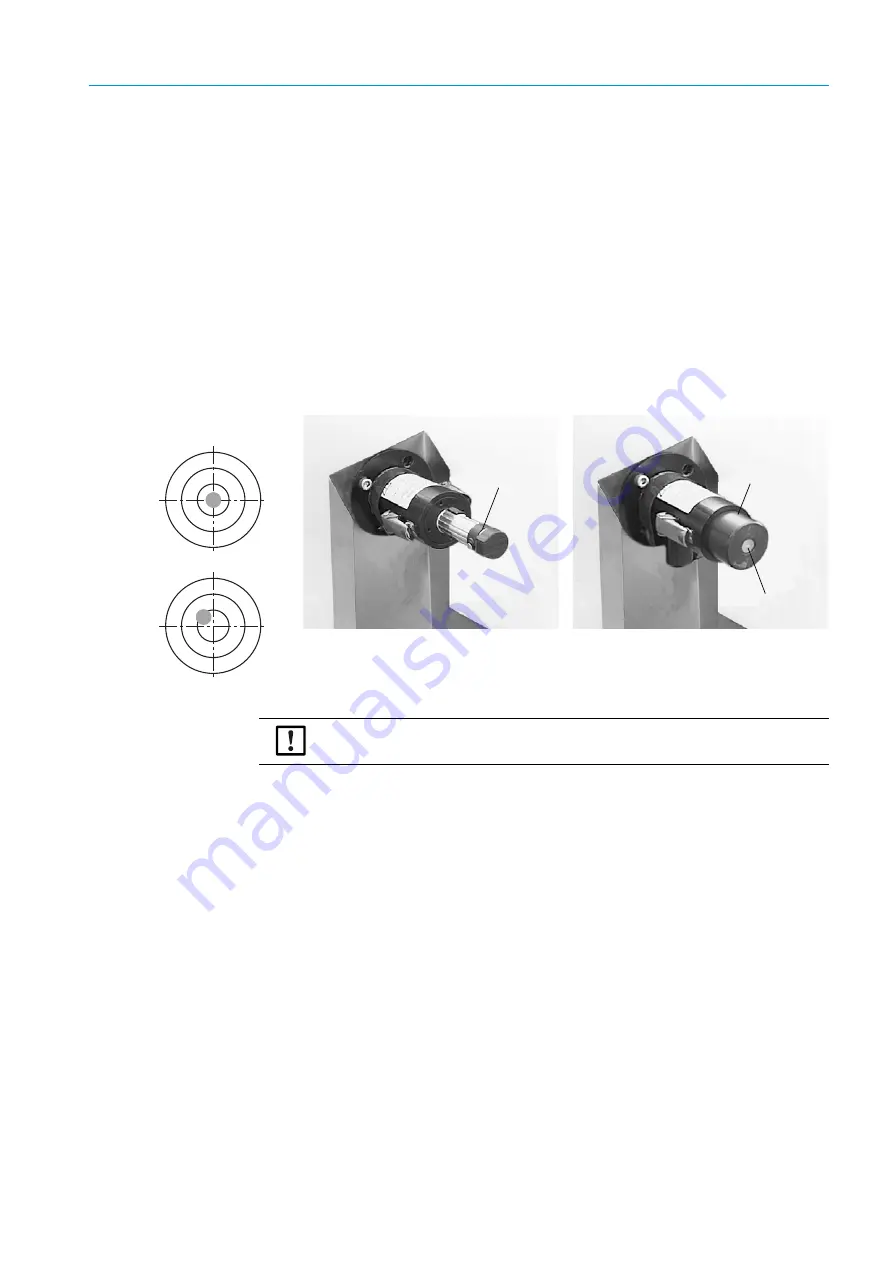
Align the purge air fixtures optically using the adjustment device.
▸
Fasten the sender and receiver on the purge air fixtures.
Fig. 22: Alignment using the adjustment device (lamp, tube)
Starting zero adjust
▸
Press CAL on the operating panel of the control unit to start the zero adjust (
“Performing zero adjust”, page 69
).
NOTE:
Do not change the alignment of the assembly brackets.
Tube
Focusing screen
Lamp
Incorrect
Correct
Light point on the focusing screen


