Chapter 10
Operating Instructions
ICR845-2 Image Code Reader
182
©
SICK AG · Division Auto Ident · Germany · All rights reserved
8012377/ 0000/ 2008-01-30
Appendix
Fig. 10-4:
CLV-Setup: "Code Properties Parameters" tab ............................................. 129
Fig. 10-5:
CLV-Setup: "Reading Configuration" tab ....................................................... 129
Fig. 10-6:
CLV-Setup: "Code configuration" tab............................................................. 130
Fig. 10-7:
CLV-Setup: "Data Matrix" tab ......................................................................... 130
Abb. 10-8:
CLV-Setup: "Code configuration" tab............................................................. 131
Fig. 10-9:
CLV-Setup: "Data Matrix" tab ......................................................................... 131
Fig. 10-10:
CLV-Setup: "Optimisation" tab ....................................................................... 132
Fig. 10-11:
CLV-Setup: "Code Properties Parameters" tab ............................................. 133
Fig. 10-12:
Limiting the active image recording area of the matrix sensor................... 133
Fig. 10-13:
CLV-Setup: "Code Properties Parameters" tab ............................................. 134
Fig. 10-14:
CLV-Setup: Results of the AutoBaud detect function .................................. 140
Fig. 10-15:
User interface of the "CLV-Setup" configuration software........................... 141
Fig. 10-16:
CLV-Setup: Entering commands in the Terminal Emulator ......................... 147
Fig. 10-17:
Wiring the "Sensor 2" switching input for triggering the teach-in of
match code 1 and for automatic activation of the code comparison......... 152
Fig. 10-18:
Auxiliary input via the auxiliary interface of the ICR845-2 .......................... 160
Fig. 10-19:
CLV-Setup: Auxiliary input via the Terminal Emulator.................................. 161
Fig. 10-20:
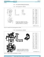
Dimensions of the mounting bracket no. 2025491 .................................... 169
Fig. 10-21:
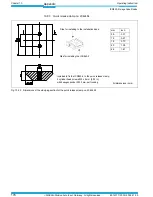
Dimensions of the mounting bracket no. 2039465 .................................... 169
Fig. 10-22:
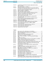
Dimensions of the clamping section for the quick release clamp
no. 2042484 .................................................................................................. 170
Fig. 10-23:
Copy of the EC Declaration of Conformity (page 1, scaled down) .............. 178
Fig. 10-24:
Scannable 1D codes with various module widths (print ratio 2:1)/
2D code........................................................................................................... 187


