Operating Instructions
Chapter 5
ICR845-2
Electrical installation
8012377/0000/2008-01-30
©
SICK AG · Division Auto Ident · Germany · All rights reserved
37
5.5
Performing electrical installation
RF interferences in case of use in residential areas!
The ICR845-2 Image Code Reader is exclusively intended for use in industrial areas.
1.
Connect or disconnect current linkages only under de-energised conditions.
2.
Wire cross-sections and their correct protection have to be selected and implemented
according to valid engineering standards.
3.
Check carefully the wiring before switching on the supply voltage for the connection
module/the ICR845-2 after finishing the electrical installation.
5.5.1
Connecting the power supply for the ICR845-2
The ICR845-2 requires a supply voltage of 15 to 30 V DC (functional extra-low voltage in ac-
cordance with IEC 364-4-41 (VDE 0100 Part 410)). The ICR845-2 has a power consumption
of max. 13 W (when switching outputs are not connected).
The functional extra-low voltage can be generated by using a safety isolating transformer
pursuant to IEC 742.
Important
The output circuit must be electrically insulated from the input circuit. This is usually crea-
ted by means of a safety transformer in accordance with IEC 742.
The ICR845-2 is supplied with 15 to 30 V DC via the CDB620 or CDM420 Connection Mod-
ule. If an optional CMF400 fieldbus gateway or a CMD400 Connection Module Display is ad-
ditionally used in the CDM420, the ICR845-2 is supplied with 18 to 30 V DC.
If the CMP400 Power Supply Module is used in the CDM420, a mains voltage of 100 to
250 V AC/50 to 60 Hz is required for the CMP400.
Important
To ensure that the incoming supply cables are protected against short-circuits/overloads,
the wire cross-sections must be dimensioned and protected in accordance with valid stand-
ards.
Use a wire cross-section of al least 0.15 mm
2
(26 AWG) when connecting the supply voltage.
Connecting the power supply:
When connecting the ICR845-2 via the connection module CDB620 or CDM420, the data
and function interfaces of the ICR845-2 are connected together with the supply voltage to
the connection module. The Ethernet interface is not routed via the connection module.
1.
Ensure that the power supply to the connection module is switched off.
2.
Connect the 15-pin cable plug on the ICR845-2 to the corresponding device socket on
the CDB620 or CDM420 and screw it tightly.
The connection cable can be extended by 2 m (6.56 ft) using the extension cable
no. 6010075. The sealing no. 4038847 remains the enclosure rating IP 65 on the plug-
in connection.
Important
If the ICR845-2 is not connected via the connection module CDB620 or CDM420, use the
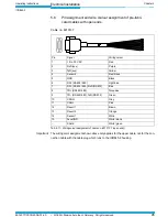
cable no. 6010137with 15-pin D-Sub HD socket and open end to connect the ICR845-2.
The wire colour assignment is shown in
Chapter 5.6 Pin assignment and wire coulour assi-
gnment of pre-fabricated cables with open ends, Page 45
.


