Chapter 6
Operating Instructions
ICR845-2 Image Code Reader
70
©
SICK AG · Division Auto Ident · Germany · All rights reserved
8012377/ 0000/ 2008-01-30
Startup and configuration
6.7
Establish communciation with the ICR845-2 manually
6.7.1
Configuring connection of the auxiliary interface (RS 232)
1.
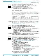
In CLV-Setup, click on
in the toolbar (AutoBaud-Detect) or select A
UTO
B
AUD
-
DETECT
under O
PTIONS
in the menu bar.
CLV-Setup scans the serial interface by varying the communication parameters and
sends a telegram to the ICR845-2 repeatedly. As soon as a reply from the ICR845-2 is
detected, CLV-Setup conveys the values found for the communication parameters.
CLV-Setup displays "
Connected"
in the status bar on the bottom, right-hand side.
2.
Confirm the A
UTO
D
ETECT
dialog box with "OK".
CLV-Setup displays the detected ICR845-2 type in a separate dialog box and asks you
whether you want to upload the current parameter set from the ICR845-2.
3.
Confirm the dialog box with "Yes".
CLV-Setup then copies the current parameter set from the RAM of the ICR845-2 to its
database and displays the values on the tabs.
6.7.2
Configuring connection of the Ethernet interface (static address)
TIP
For rapid and easy establishing communication via Ethernet (with adaption of the ICR845-
2’s IP address to the customer-specific conditions) CLV-Setup provides the CLV-Assistant
via the T
OOLS
menu. See also
Chapter 6.3.3 Configuring and starting the Ethernet commu-
nication with the Assistant, Page 50
. The ICR845-2 has to connect using a Ethernet cable.
The ICR845-2 operates exclusively with a static IP address.
When using static IP addresses, the IP addresses of the ICR845-2 and the PC must be in
the same set of numbers. We recommend (starting with the default setting on the first star-
tup) to adapt the IP address of the ICR845-2 to the address of the PC.
1.
Connect the ICR845-2 to the PC via the serial auxiliary interface (RS 232) and establish
communication (see above).
2.
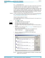
Double-click on E
THERNET
in the device tree of the ICR845-2, left-hand side.
The E
THERNET
tab is then displayed.
3.
In der TCP/ IP section, enter the required data (IP address of the ICR845-2 and subnet
mask of the network) in accordance with the customer-specific conditions.
4.
Copy the modified parameter values to the ICR845-2.
To do so, press the [F4] key (download) and select the "permanent" storage option.
5.
Restart the ICR845-2.
To do so, switch off and switch on again the supply voltage.
6.
The ICR845-2 starts with the modified communication parameters for its Ethernet in-
terface.
7.
Remove the RS 232 data cable from the ICR845-2 (connection module).
8.
Connect the ICR845-2 directly to the PC using a crossover cable or connect the ICR845-
2 to the Ethernet network using a patch cable.
9.
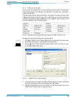
Select I
NTERFACE
under O
PTIONS
in the menu bar.
10. Activate the TCP/ IP protocol of the ICR845-2 in the I
NTERFACE
O
PTIONS
dialog box.
In the IP A
DDRESS
section enter the same IP address as choosen on the E
THERNET
tab.
Confirm the dialog box with "OK".
CLV-Setup attempts to establish communication with the ICR845-2. If the attempt has
been successful, CLV-Setup loads the current parameter values of the ICR845-2 for dis-
playing in the tabs.

