Operating Instructions
Chapter
4
LD-MRS
Mounting
8012948/ZMQ0/2017-06-09
©
SICK AG · Germany · All rights reserved · Subject to change without notice
57
4.3
Mounting and adjustment of the device
After mounting the LD-MRS, adjust the matching angles and the distance to the reference
plane.
4.3.1
Mounting the LD-MRS
For mounting the LD-MRS safely at the mounting location, 4 M6 screws with washers and
lock washers are required. The supply voltage of the LD-MRS must be switched off.
4.3.2
Distance between LD-MRS and object/surface to be monitored
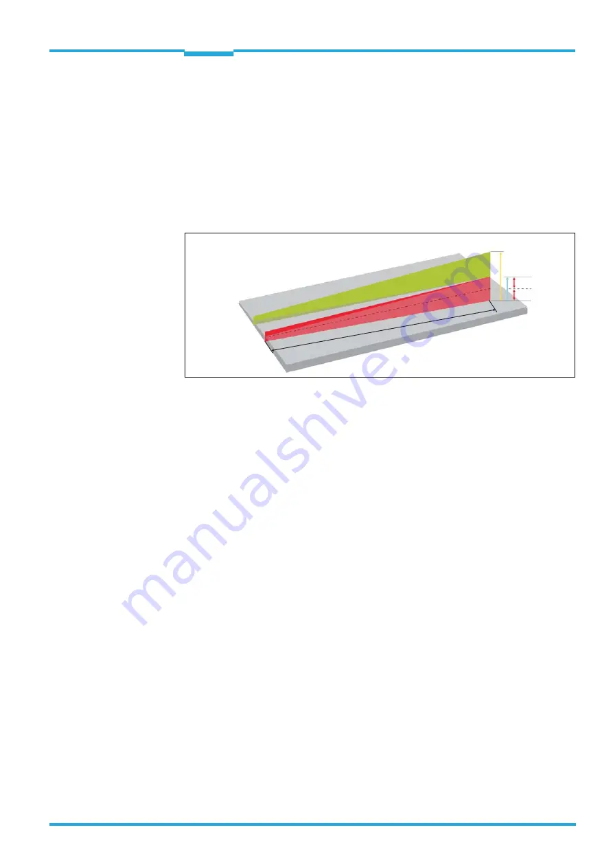
Caption:
a
vertical beam expansion for four layers
b
vertical beam expansion for two layers (one laser pulse)
c
vertical beam expansion for one layer
s
distance in mm
The reference plane for the required distance to the floor/wall is the sensor point of origin,
see
Chapter 9.2.2 LD-MRS laser measurement sensor: Dimensions, Page 98
.
The distance-dependant beam expansion can be calculated with this formula:
–
vertical beam expansion for one layer = distance × 0.014
–
horizontal beam expansion for one layer = distance × 0.0014
For some example values see
,
and
.
Fig. 4-1:
Beam expansion
a
b
c
c
s


