Chapter
5
Operating Instructions
Laser measurement sensor LD-MRS
66
©
SICK AG · Germany · All rights reserved · Subject to change without notice
8012948/ZMQ0/2017-06-09
Electrical installation
5.3
Electrical connections and cables
The connections of the LD-MRS consist of three round plug-in connections. These connec-
tions lead to the following interfaces:
•
Ethernet data interface
•
Data interface RS-232 (auxiliary data interface)
•
Data interface CAN
•
synchronization interface
•
Power supply
5.3.1
Pin assignment of the connections
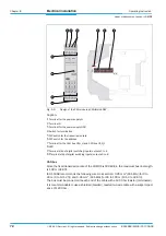
Connection "Ethernet"
Connection "Data interfaces/Synchronization
Pin
Signal
Function
1
RX–
Receive–
2
TX+
T
3
TX–
Transmit–
4
RX+
Tab. 5-1: Pin assignment of the 4-pin socket (round plug-in connection) "Ethernet"
Pin
Signal
Function
1
TxD
RS-232, Transmit
2
Sync-out
Sensor Sync.
3
Sync-in
Sensor Sync.
4
Data GND (Sync-in)
Data Ground
5
Data GND (Sync-out)
Data Ground
6
Data GND (TxD, RS-232)
Data Ground
7
RxD
RS-232, Receive
Tab. 5-2: Pin assignment of the 12-pin plug "data interfaces/synchronization" (round plug-in
connection)
1
4
2
3
5
8
6
7
1
12
2
10
11
4
3
9


