Operating Instructions
Chapter
5
LD-MRS
Electrical installation
8012948/ZMQ0/2017-06-09
©
SICK AG · Germany · All rights reserved · Subject to change without notice
73
Caption:
1
LD-MRS
2
CAN module
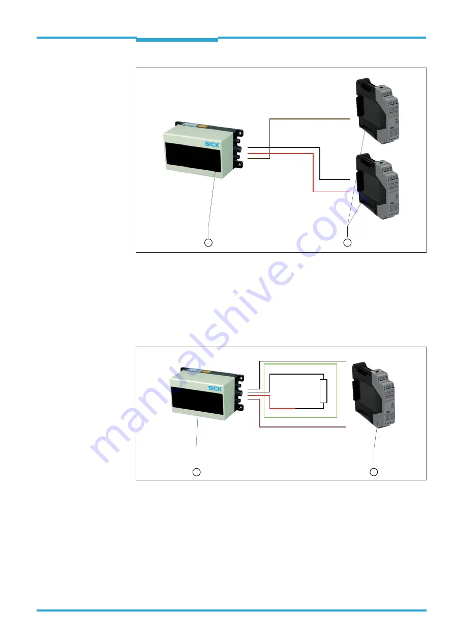
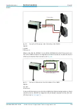
When a cable (Part No. 2050647 (2 m (6.56 ft))/ 2050648 (8 m (26.2 ft))) is used to con-
nect to the LD-MRS in maximum configuration, both CAN modules are connected to the end
of the bus via the 9-pin D-sub connector, see
Caption:
1
LD-MRS
2
CAN module
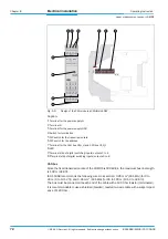
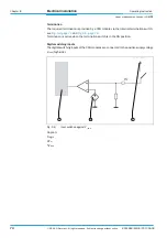
If only one CAN module is connected to the LD-MRS, the CAN terminating resistance (D-Sub
connector) Part no. 6042511 is integrated in the termination resistance for the other end
of the bus, see
.
Fig. 5-6:
Connect two CAN modules to the CAN interface of the LD-MRS
CAN_H1 (black)
CAN_L1 (brown)
CAN_H2 (black)
CAN_L2 (red)
1
2
Fig. 5-7:
Connect one CAN module to the CAN interface of the LD-MRS
CAN_H1 (Pin 7) (black)
CAN_H2 (Pin8) (black)
CAN_L2
Int. termination resistance (green)
(Pin4) (red)
CAN_L1 (Pin 2) (brown)
1
3
120Ω


