Chapter
5
Operating Instructions
Laser measurement sensor LD-MRS
80
©
SICK AG · Germany · All rights reserved · Subject to change without notice
8012948/ZMQ0/2017-06-09
Electrical installation
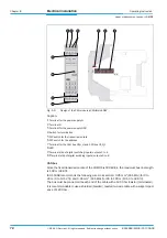
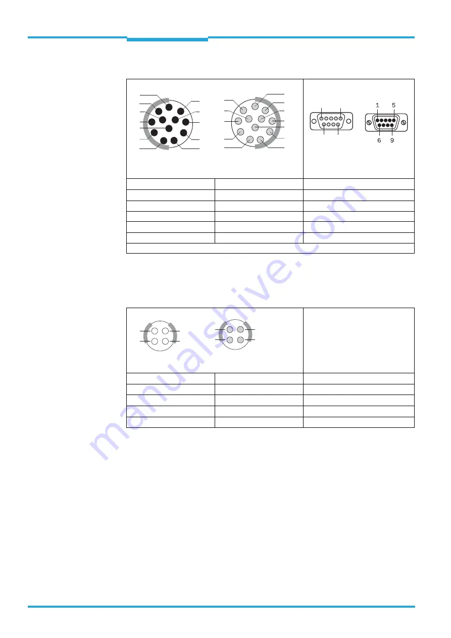
Cable Part no. 2054647, 2054648 ("CAN" connecting cable)
5.5.2
Wire colour assignment of the assembled cables
Cable no. 2049823, 2049824, 2049825, 2067524 (supply cable)
12-pin plug (round plug-in connection)
9-pin D-Sub socket
Pin*)
Signal
Pin
1 .. 8
not assigned
–
9
CAN_L1
2
10
CAN_H1
7
11
CAN_L2
4
12
CAN_H2
8
*) Twisted wire pair: CAN_L1 (9) with CAN_H1 (10); CAN_L2 (11) with CAN_H2 (12)
Tab. 5-9: Pin assignment of the CAN connecting cable
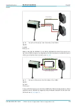
4-pin socket (round plug-in connection)
Open end with 2 bunch pin plugs
Pin
Signal
Plug / wire color
1
Power GND
black / white
2
V
s
red / yellow
3
V
s
red / green
4
Power GND
black / brown
Tab. 5-10: Wire colour assignment of the supply cable
5
8
6
7
1
12
2
10
11
4
3
9
View from the front
5
8
6
7
1
12
2
10
11
4
3
9
View from the
soldering side
1
5
6
9
View from
the front
View from the
soldering side
1
4
2
3
View from the front
View from the
soldering side
1
4
2
3


