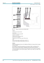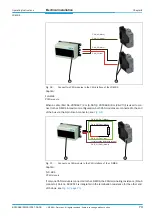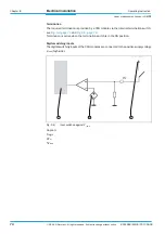
Operating Instructions
Chapter
6
LD-MRS
Commissioning and configuration
8012948/ZMQ0/2017-06-09
©
SICK AG · Germany · All rights reserved · Subject to change without notice
85
6.5
Conclusion and test measurement
Use the graphic scan display in SOPAS-ET to verify the generated measurements and mea-
suring range online.
1. In the project tree, select LD-MRS /
MONITOR
/
EVALUATION
MONITOR
.
2. To start measurement, click the button D
ISPLAY
SCAN
LINE
.
3. Compare the measured line with the desired results.
Important
– The S
CAN
DISPLAY
on the
MONITOR
depends on the available power of the computer and
does
not
occur in real time. Consequently, not every measurement is visualized.
4. After the test measurement is over, permanently save the configuration on the LD-MRS:
In the menu, go to LD-MRS/P
ARAMETERS
/S
AVE
PERMANENTLY
.
6.6
Synchronization
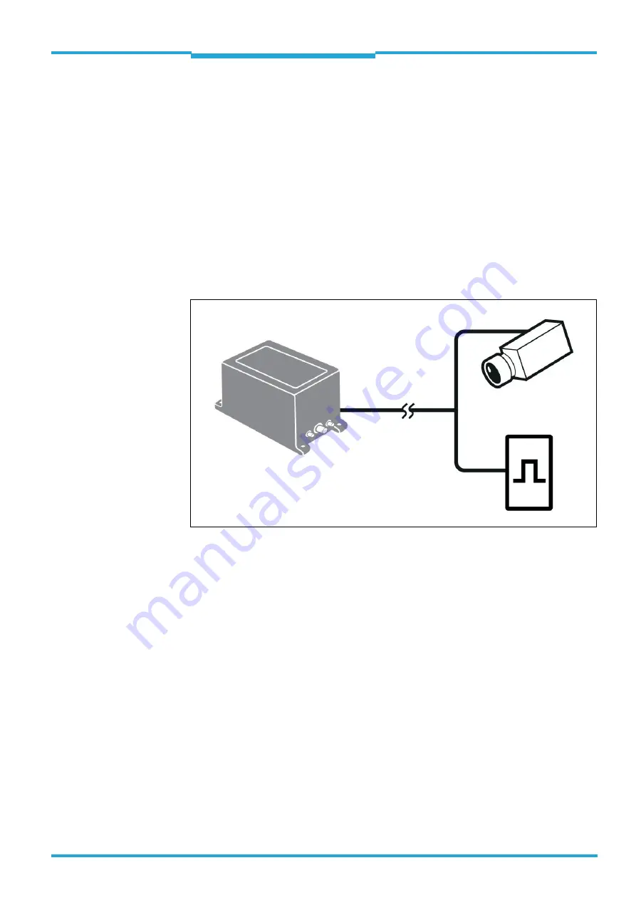
Caption:
1
LD-MRS
2
"Data interfaces/synchronization" connecting line
3
External device (e.g. camera; optional)
4
External synchronization pulse signal generator (optional)
In a fusion system with an LD-MRS and an external device (e. g. a camera), the LD-MRS
must be synchronized with the external component to minimize time shift during data col-
lection of both components.
This reduces the necessity of scan data corrections during processing.
During the synchronization process, the LD-MRS adjusts its scanning frequency (in a small
range) so that the measurement in a selected angle happens at the time the external device
presents a synchronization pulse.
Another option is to define the LD-MRS as master which presents its synchronization pulse
to the external device, which can adjust its processing frequency of measurement (e. g. tak-
ing pictures) to this synchronization signal.
Fig. 6-2:
Scheme of the data flow in a system with one LD-MRS and up to two external devices


