Operating Instructions
Chapter
6
LD-MRS
Commissioning and configuration
8012948/ZMQ0/2017-06-09
©
SICK AG · Germany · All rights reserved · Subject to change without notice
87
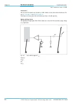
The voltage level to detect an external trigger signal must have level E/A-232 (formerly RS-
232).
The LD-MRS detects a logical positive flank as the moment of synchronization, see T
SyncTime
.
6.6.2
Synchronization systems
There are three possible synchronization systems:
•
LD-MRS and external device synchronized by the LD-MRS
•
LD-MRS and external device synchronizing the LD-MRS
•
LD-MRS and two external units, one of which synchronizes the LD-MRS, the other being
synchronized by the LD-MRS
The external unit can also be a different LD-MRS.
Each LD-MRS starts as a master unit, sending trigger points to the next unit. The LD-MRS
always sets the output signal to t
Pulse_out
= 20
μ
s; see the red output signal in
.
When the trigger input receives a transition from low to high, the LD-MRS switches to the
salve mode. This stops the further active sending of the Sync Pulse. The device then only
copies and transmits the master trigger.
The external synchronization signal should remain in high state for at least t
Pulse,min
=
10
μ
s, see blue input signal in
If no other external trigger is present, the LD-MRS switches back to master mode after ap-
prox. 300 ms.
6.7
Switching off the LD-MRS
Switch off the supply voltage of the LD-MRS.
The parameter set most recently stored in the LD-MRS remains valid.
Fig. 6-4:
LD-MRS: Sync IN and Sync Out pulse


