Operating Instructions
Chapter
5
LD-MRS
Electrical installation
8012948/ZMQ0/2017-06-09
©
SICK AG · Germany · All rights reserved · Subject to change without notice
75
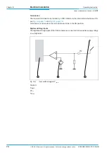
Digital switching outputs
The digital switching output of the CAN modules are connected to the positive supply volt-
age V
+PWR
(high side driver).
Caption:
1
logic
2
impedance R
in
3
V
+PWR
5.4.3
Configuring the CAN module
Setting the CAN address
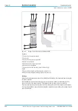
For addressing in the CAN bus, the address range 1 to 127 is available. By default, the ad-
dress of theLD-MRS is 1. Each address assigned to a device may only occur once (such as
10, 11, 12).
Important
Switch 8 must always be in the 0 position (OFF).
The switches may never all be in the 0 position (OFF) at the same time.
In this configuration, the CAN module will not start.
Fig. 5-9:
A circuit diagram of digital I/O terminal (high side driver)
1
3
2
Fig. 5-10:
DIP switch for address (example: address 9)
1
2
3
4
5
6
7
8
OFF


