5.3.5
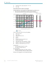
Field of view diagrams
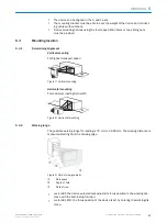
Take into account the following aspects in application design:
•
Field of view geometry of the device and position of the field of view in the space
in front of the device
•
Possible reading angles at which the codes can occur with respect to the device
•
For the planned working distance: resultant field of view length and width and min‐
imum possible resolution
0
200 x 160
400 x 320
600 x 480
800 x 640
1000 x 800
1200 x 960
100 x 80
400 x 320
200 x 160
300 x 240
0
0
200
400
600
800
1000
1200
1400
1600
1800
2000
a
b
0
200
400
600
100
300
500
Min. resolution in mm
3
1D code
4
2D code
5
0.4
0.6
0.8
0.1
0.3
0.5
0.7
0.9
1.1
1.3
0.2
1.2
1.4
1.6
1.0
Min. resolution in mm
3
1D code
4
2D code
5
0.1
0.2
0.3
0.4
0.15
0.25
0.35
0.4
0.2
0.3
0.5
0.1
0.05
a: f = 9.6 mm
b: f = 17.1 mm
Working distance/focus position in mm
6
a
b
Working distance/focus position in mm
6
Field of view in mm²
1
Field of view in mm²
1
Complete area
2
Narrow area
8
7
7
Figure 12: Field of view diagram Lector621/Lector621 ECO
1
Field of view in mm
2
2
Overall range
3
Minimum resolution in mm
4
1D code
5
2D code
6
Working distance/Focus position in mm
MOUNTING
5
8022502/15NT/2020-02-11 | SICK
O P E R A T I N G I N S T R U C T I O N S | Lector621
29
Subject to change without notice


