


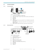
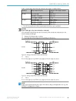
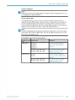
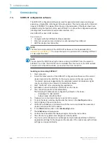
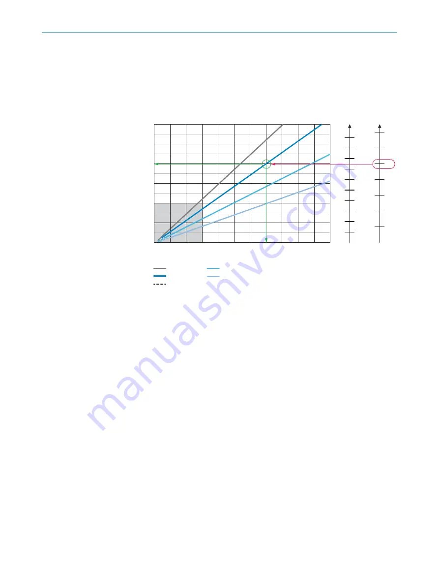
Interpretation aid for the field of view diagrams
Using the diagrams, you can determine the following data for each device type:
•
The maximum working distance for a selected code resolution
•
The dimensions of the field of view that is available for this distance
Example field of view diagram for Lector632 S-mount:
Min. resolution in mm
3
1D code
4
2D code
5
Field of view: H x V (mm)
1
0
0
200
400
600
800
1,000 1,200 1,400 1,600 1,800 2,000 2,200
400 x 300
600 x 450
800 x 600
1,000 x 750
1,200 x 900
200 x 150
0.1
0.3
0.5
0.7
0.9
0.2
0.4
0.6
0.8
1.0
1.2
1.4
a
b
c
d
a: f = 9.6 mm
b: f = 12.5 mm
c: f = 17.5 mm
d: f = 25.0 mm
Optional spacer rings required
à
7
8
9
Working distance/focus position in mm
6
ß
Complete area
2
1
Field of view: horizontal x vertical (mm)
2
Overall range
3
Minimum resolution in mm
4
1D code
5
2D code
6
Working distance/Focus position in mm
7
Selected code resolution
8
Focal length of lens, here example for f = 12.5 mm
9
Reading off: resultant maximum working distance
ß
Reading off: resultant field of view (mm x mm)
à
Optional spacer ring required
Given (in red):
•
Code resolution for 2D code
7
: 1.0 mm
•
Focal length of lens
8
: 12.5 mm
Read off (in green):
•
Maximum working distance
9
: approx. 1,400 mm
•
Field of view
ß
: approx. 800 mm x approx. 600 mm
Both axes of the diagrams must be interpreted linearly.
5.6
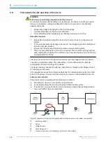
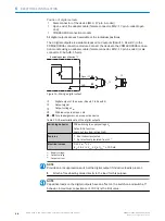
Mounting the device
1.
Mount the device in a suitably prepared mounting system with M5 screws using
the threaded mounting holes or sliding nuts provided.
MOUNTING
5
8018071/1E1C/2021-12-16 | SICK
O P E R A T I N G I N S T R U C T I O N S | Lector63x Flex C-mount and S-mount
35
Subject to change without notice


