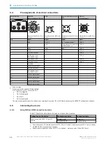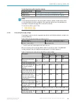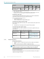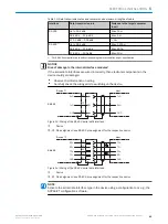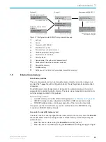
Wiring data interfaces via a connection module
Connection modules
Data interface
Reference
CDB650-204
RS-232
see "Wiring serial host inter‐
face RS-232 of the device in
CDB650-204", page 73
CDB650-204
RS-422
see "Wiring serial host inter‐
face RS-422 of the device in
CDB650-204", page 73
CDM420-0006
RS-232
see "Wiring serial host interface
RS-232 of the device in the
CDM420-0006", page 86
CDM420-0006
RS-422
see "Wiring serial host interface
RS-422 of the device in the
CDM420-0006", page 86
Termination of the RS-422 data interface
Termination can be implemented in the connection module via switches.
Additional information on this can be found in the operating instructions for the relevant
connection module.
6.5.4
Wiring the CAN interface
NOTE
Activate the CAN data interface in the device with a configuration tool, e.g., the configu‐
ration software SOPAS ET.
Make further settings in the device corresponding to the function of the device in the
system configuration.
Wiring CAN interfaces via a connection module
Connection modules
Interface
Reference
CDB650-204
CAN
see "Wiring the CAN interface of
the device in the CDB650-204",
page 74
CDM420-0006
CAN
see "Wiring the CAN interface of
the device in the CDM420-0006",
page 87
6.5.5
Wiring the digital inputs
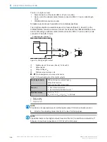
The device has 2 switching digital inputs (Sensor1, Sensor 2).
Functions (examples)
•
Start and end external reading cycle.
•
Feed in incremental signal.
Position of digital inputs
•
Male connector of the device (M12, 17-pin, A-coded)
•
Adapter cable (female connector, M12, 17-pin, A-coded/male connector, D-Sub-
HD, 15-pin)
•
Open end of the adapter cable (female connector, M12, 17-pin, A-coded/open
end)
All digital inputs are available at the individual positions.
6
ELECTRICAL INSTALLATION
46
O P E R A T I N G I N S T R U C T I O N S | Lector63x Flex C-mount and S-mount
8018071/1E1C/2021-12-16 | SICK
Subject to change without notice


