


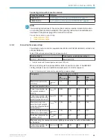


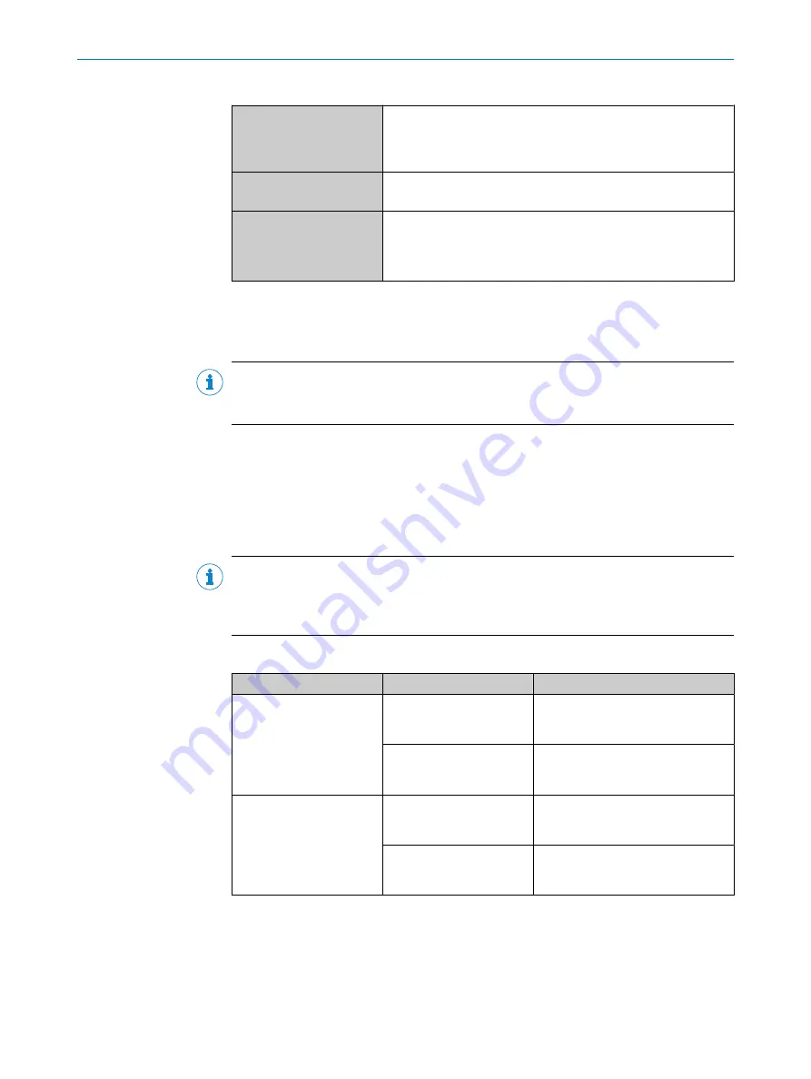
Table 14: Characteristic data of the digital inputs (Sensor 1, Sensor 2)
Switching behavior
Power to the input starts the assigned function, e.g. start of the
internal reading interval of the device.
Default: active high
Debouncing: 10 ms (standard)
Features
•
Opto-decoupled, reverse polarity protected
•
Can be wired to PNP output of a trigger sensor
Electrical values
The electrical values are identical for all digital inputs of the
device.
Low: V
in
1)
≤ 2 V; I
in
2)
≤ 0.3 mA
High: 6 V ≤ V
in
≤ 30 V; 0.7 mA ≤ I
in
≤ 5 mA
1)
Input voltage V
in
.
2)
Input current I
in
.
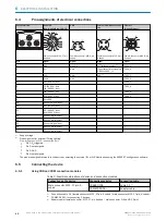
Function assignment
NOTE
Assign the functions for the digital inputs in the device using a configuration tool, e.g.,
the configuration software SOPAS ET.
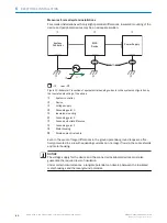
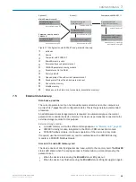
External digital inputs
If the CMC600 cloning module is used in the CDB or CDM connection module, 2
additional external digital inputs (external input 1, external input 2) are available. The
external digital inputs are located at the terminals of the connection module. For the
electrical characteristic data of the external digital inputs, see the connection diagrams
for the connection modules in these operating instructions.
NOTE
The external digital inputs are software-controlled and therefore do not offer the same
timing precision as physical digital inputs. The external digital inputs may not be suita‐
ble for time-critical applications.
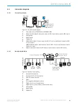
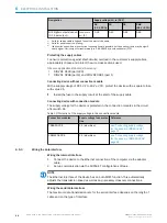
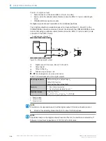
Wiring digital inputs via connection module
Connection modules
Digital inputs
Reference
CDB650-204
SENS/IN 1
SENS/IN 2
see "Wiring digital inputs of
the device in the CDB650-204",
page 76
External input 1 (EXT. IN 1)
External input 2 (EXT. IN 2)
see "Wiring the external digital inputs
of the device in the CDB650-204",
page 78
CDM420-0006
Sensor 1
Sensor 2
see "Wiring digital inputs of the
device in the CDM420-0006",
page 89
External input 1 (AUX In 1)
External input 2 (AUX In 2)
see "Wiring the external digital inputs
of the device in the CDM420-0006",
page 91
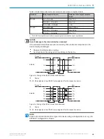
6.5.6
Wiring the digital outputs
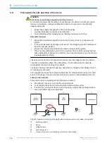
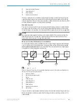
The device has 2 (Result 1, Result 2) or 4 (Result 1 to Result 4) switching digital
outputs. The digital outputs are used to signal events in the read operation. Different
functions can be assigned to the digital outputs independently of each other for this
purpose. If the assigned event occurs, then the corresponding digital output becomes
live after the end of the read cycle for the selected pulse duration, for example (default).
ELECTRICAL INSTALLATION
6
8018071/1E1C/2021-12-16 | SICK
O P E R A T I N G I N S T R U C T I O N S | Lector63x Flex C-mount and S-mount
47
Subject to change without notice


