á
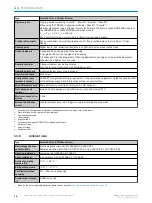
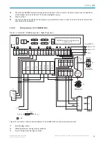
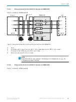
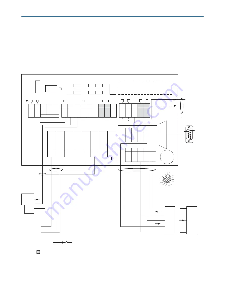
The optional CMC600 parameter cloning module is required in the connection module in order to use the additional
external digital inputs and outputs of the device (highlighted in gray).
â
Other functions
ã
Can also be used as an alternative stop trigger (e.g., photoelectric sensor) or travel increment (incremental encoder),
depending on the application
13.2.2
Wiring overview of the CDB650-204
Device = Lector63x = V2D63xx-xxxxBx, 1 digital input used
CMC600 parameter cloning module
(optional)
2
Term CAN
Term 485
RS
SGND - GND
422 485
ON
OFF
NO
YES
ON
OFF
ON
OFF
S2
S3
S7
S6
S4
CMC
ON
OFF
POWER
S1
30
31
32
33
34
C
A
N
_H
C
A
N
_L
T
+
R
+
GN
D
40
41
42
43
44
C
A
N
_H
C
A
N
_L
T
‒
/
T
xD
R
‒
/
R
xD
GN
D
A
U
X i
nt
e
rf
a
c
e
5
U
IN
U
IN
GN
D
GN
D
S
hi
e
ld
S
hi
e
ld
S
hi
e
ld
S
hi
e
ld
1
2
3
4
5
6
7
8
LEDs
=
ß
V
S
V
S
Out
GND
Result 1
4
-
e.g. PLC
3
GND
Result 2
4
-
Device
9
Pin
2: RxD
3: TxD
5: GND
Host
TD‒
TD+
RD+
RD‒
TxD
Host
RxD
GND
GND
RS-232
2
A
T
F
SENSOR
50
51
52
53
54
R
E
S
/
O
UT
3
R
E
S
/
O
UT
4
Ext. Illum.
T
R
L
+
GN
D
20
21
22
23
24
GN
D
R
E
S
/
O
UT
1
R
E
S
/
O
UT
2
E
X
T.
O
UT
1
E
X
T.
O
UT
2
10
11
12
13
14
15
16
17
18
U
IN
*
U
IN
*
S
GN
D
S
GN
D
S
GN
D
E
X
T.
IN
1
S
E
N
S
/
IN
1
S
E
N
S
/
IN
2
E
X
T.
IN
2
RS-232
3
1
7
2
6
5
4
8
13
14
17
15
9
10
12
16
11
8
1
CDB650-204
V
S
-
U
IN
-
F
S 1
-
U
IN
*
6
7
à
5
1
9
6
RS-422
-
Computer
Figure 19: Connection of device and peripherals to the CDB650-204 connection module (overview).
1
External trigger sensor
2
CMC600 parameter cloning module (optional)
3
E.g., PLC (programmable logic controller)
ANNEX
13
8018071/1E1C/2021-12-16 | SICK
O P E R A T I N G I N S T R U C T I O N S | Lector63x Flex C-mount and S-mount
71
Subject to change without notice

