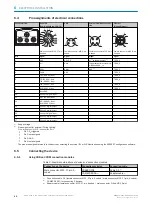
1
2
3
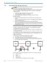
Figure 5: Screw in the S-mount lens
1
Limit stop: Screw in the lens to the limit stop.
2
Light inlet
3
S-mount lens
6.
If required, mount the spacer. Maximum recommended torque: 65 Ncm.
7.
If required, plug the illumination unit connector into the housing.
8.
Mount the illumination unit using the 4 screws. Use the enclosed SW 2 hexagon
key for this purpose.
9.
Mount the optional filter and filter holder.
10. Mount the protective optics cover.
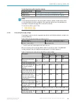
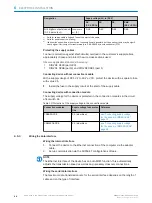
Table 8: Spacer rings depending on the working distance
Working distance in
mm
Spacer rings in mm (depending on the focal length of the lens)
9.6 mm
17.5 mm
25 mm
50 … 65
-
1)
2.3 +3
2)
-
3)
60 … 95
-
1)
1.5 +2,3
2)
-
3)
70 … 90
-
1)
2,3
1.5 +1.5 +1.5 +3
80 … 100
-
1)
2,3
1.5 +2.3 +3
90 … 120
-
1)
1,5
2.3 +3
100 … 130
-
1)
1,5
1.5 +3
110 … 170
-
1)
1,5
1.5 +2.3
150 … 210
-
1)
-
1)
3
> 210
-
1)
-
1)
-
1)
1)
No spacer rings required.
2)
This working distance requires longer spacers, a longer illumination unit connector (part number:
2079501), and a taller optics protective hood (part number: 2079127).
3)
Working distance not possible with this lens.
5.5
Mounting location
5.5.1
Work area
Depending on the device type, the working range is between 50 mm and 2,200 mm.
The field of view is determined by the focus position, the focal length of the lens, and
the working distance. The necessary working distance can be determined from the field
of view diagram,
see "Field of view diagrams", page 31
.
5.5.2
Mounting bracket and reflection prevention
In order to avoid reflections from the surfaces to be scanned, mount the device so that
it is tilted from the perpendicular to the surface.
MOUNTING
5
8018071/1E1C/2021-12-16 | SICK
O P E R A T I N G I N S T R U C T I O N S | Lector63x Flex C-mount and S-mount
29
Subject to change without notice


