background image

13.3.9

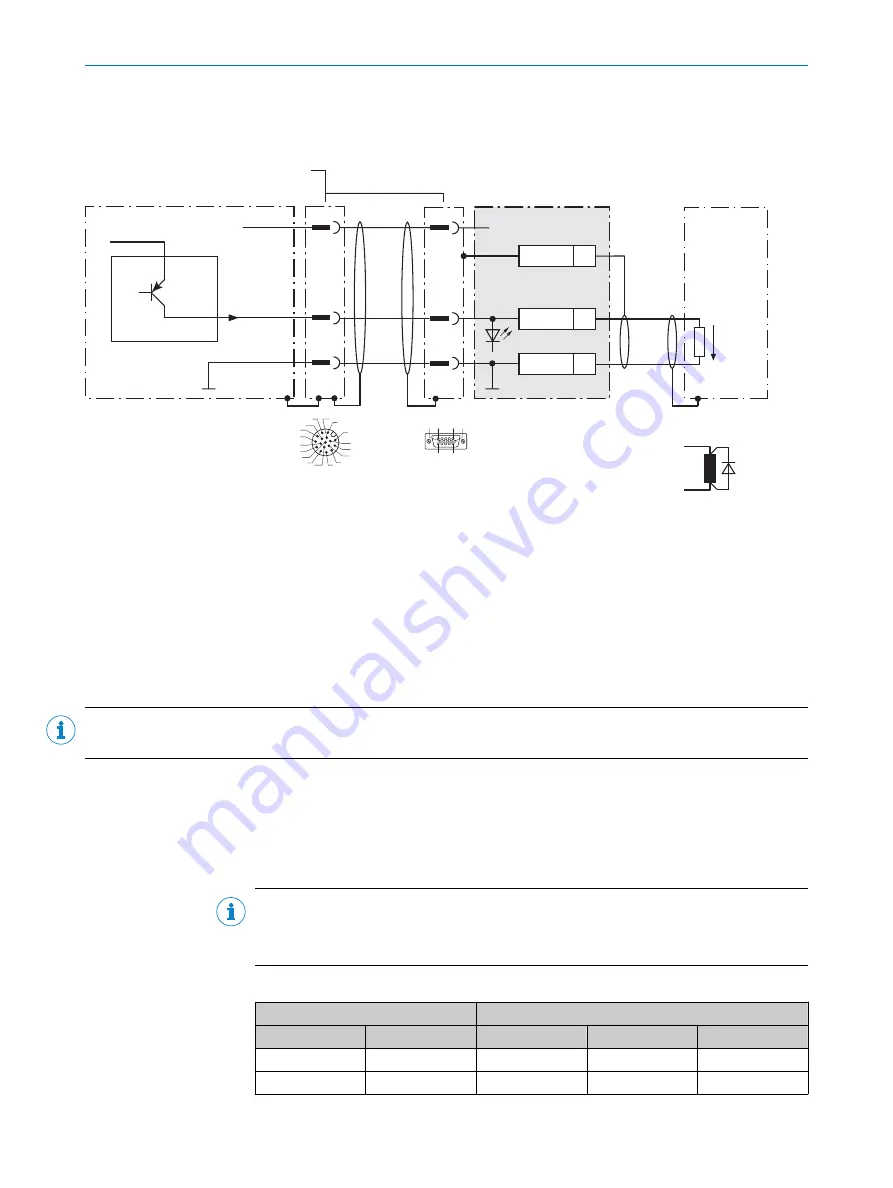
Wiring digital outputs of the device in the CDM420-0006

Device = Lector63x = V2D63xx-xxxxBx

Device 

1

CDM420-0006

Load (e.g. PLC) 

4

C

5


.

E

Result 

D

13

GND

5

Shield

+24 V* (V

S

V

S

GND

V

out


Result 

A

GND

B

1

2

1

For inductive load: 

6

5

2

3

3

1

7

2

6

5

4

8

13

14

17

15

9

10

12

16

11

8

7

1

10

15

6

11

5

Figure 40: Wire the digital output in the CDM420-0006 connection module.

1

Device

2

Supply voltage V

S

3

Adapter cable (female connector, M12, 17-pin, A-coded/male connector, D-Sub-HD, 15-pin)

4

Load (e.g. PLC)

5

Output voltage V

out

6

With inductive load: see note

7

Connection module: female connector, D-Sub-HD, 15-pin

8

Device: male connector, M12, 17-pin, A-coded

NOTE

Digital outputs are omitted due to the 15-pin adapter cable.

Not available in CDM420-0006:

Result 3

Result 4

Inductive load

NOTE

Provide an arc-suppression switch at the digital output if inductive load is present.

b

Attach a freewheeling diode directly to the load for this purpose.

Table 38: Assignment of placeholders to the digital outputs

Device

CDM420-0006

Output A

Pin B

Pin C

Signal D

Terminal E

Result 1

13

12

Result 1

14

Result 2

14

13

Result 2

15

ANNEX 

13

8018071/1E1C/2021-12-16 | SICK

O P E R A T I N G   I N S T R U C T I O N S | Lector63x Flex C-mount and S-mount

93

Subject to change without notice

Summary of Contents for Lector63x Flex C-mount

Page 1: ...O P E R A T I N G I N S T R U C T I O N S Lector63x Flex C mount and S mount Image based code readers ...

Page 2: ...mits of the legal determination of Copyright Law Any modi fication abridgment or translation of this document is prohibited without the express written permission of SICK AG The trademarks stated in this document are the property of their respective owner SICK AG All rights reserved Original document This document is an original document of SICK AG 1 1 1 25 1 The certification is type dependent 2 ...

Page 3: ...rable illumination unit optional 17 3 5 Display and control elements 17 3 6 Memory card 19 3 7 Function and use 21 4 Transport and storage 22 4 1 Transport 22 4 2 Unpacking 22 4 3 Transport inspection 22 4 4 Storage 22 5 Mounting 24 5 1 Mounting instructions 24 5 2 Overview of mounting procedure 24 5 3 Preparation for mounting 24 5 4 Mounting the optics 25 5 5 Mounting location 29 5 6 Mounting the...

Page 4: ...vice 61 9 5 Repairs 61 9 6 Returns 61 9 7 Replacing the device 62 10 Decommissioning 64 10 1 Disposal 64 11 Technical data 65 11 1 Features 65 11 2 Mechanics and electronics 66 11 3 Performance 67 11 4 Interfaces 67 11 5 Ambient data 68 12 Accessories 69 13 Annex 70 13 1 Declarations of conformity and certificates 70 13 2 Connection diagrams of connection module CDB650 204 70 13 3 Connection diagr...

Page 5: ...instructions for the machine or system 1 2 Scope These operating instructions serve to incorporate the device into a customer system Instructions are given by stages for all actions required These operating instructions apply to all available device types of the product To obtain more detailed information on identifying your device type see Type code page 14 Available device types are listed on th...

Page 6: ...fication diagrams Declarations of conformity and certificates of the product family Dimensional drawings and 3D CAD dimension models of the device types in various electronic formats Other publications related to the devices described here Publications dealing with accessories NOTE Important information about the integratable VI55I illumination unit can be found in the VI55I ring illumination unit...

Page 7: ... Only the VI55I illumination units from SICK intended for integration in this application can be used as integratable illumination units SICK AG assumes no liability for losses or damage arising from the use of the product either directly or indirectly This applies in particular to use of the product that does not conform to its intended purpose and is not described in this documentation 2 1 1 Con...

Page 8: ...ing information Product should be used only in accordance with its intended use All information in these operating instructions must be strictly observed Shut down the product immediately in case of damage 2 3 Cybersecurity To protect against cybersecurity threats it is necessary to continuously monitor and maintain a comprehensive and holistic cybersecurity concept A suitable concept com prises o...

Page 9: ...nowl edge of the relevant standards and provisions to be able to carry out work on electrical systems and to detect and avoid any potential dangers independently The electrician must comply with the provisions of the locally applicable work safety regulation The following qualifications are required for various activities Table 1 Activities and technical requirements Activities Qualification Mount...

Page 10: ... Comply with the current national regulations on photobiological security of lamps and lamp systems Risk group 2 Color of the illumination visible blue light aperture angle narrow CAUTION Warning Optical radiation LED risk group 2 visible radiation 400 nm to 780 nm Potentially dangerous optical radiation Can be damaging to the eyes Do not look into the light source for extended periods of time Nev...

Page 11: ... or death Work on electrical systems must only be performed by qualified electricians The power supply must be disconnected when attaching and detaching electrical connections The product must only be connected to a voltage supply as set out in the require ments in the operating instructions National and regional regulations must be complied with Safety requirements relating to work on electrical ...

Page 12: ...ngs using the SOPAS ET configuration software 3 Attach the protective optics cover and screw it tight 4 Attach the warning label to the optics protection hood in a well visible location near the light outlet 5 If the device itself is for example integrated into a machine in such a way that the attached warning label is obscured attach further clearly visible labels to the machine close to where th...

Page 13: ...croSD card slot and the focus screw 2 Blue label round self adhesive Protection of adjusted focus setting S mount lens After adjustment of the focus setting the label can be stuck over the access opening for the focus adjustment screw 1 label as spare part 1 SICK lens cloth Clean optical surfaces e g front screen in the optics protection hood 1 Printed safety notes multilin gual Brief information ...

Page 14: ...ltage power consumption current consumption 5 MAC address 6 Date of manufacture 3 2 2 Type code The devices of the Lector63x product family are arranged according to the following type code V2D 6 x y z a b c d e f g 1 2 3 4 5 6 7 8 9 10 11 12 13 Position Description Characteristic 1 Device name V2D 2D machine vision 2 Product family 6 6xx 3 Platform housing 3 Midrange Line 4 Resolution of the imag...

Page 15: ... MH 50 mm f8 S mount lenses SX S mount module no lens Variants with S mount lens SC 9 6 mm f8 SD 12 5 mm f8 SE 17 5 mm f8 SF 25 mm f8 12 Connection variants 1 B Standalone Power Serial Data CAN I O Ethernet USB 2 13 IP protection class material of the optics protection hood front screen 0 None camera housing only 8 IP67 plastic 22 7 mm low 4 IP67 plastic 37 7 mm medium 1 IP67 plastic 60 0 mm high ...

Page 16: ...d holes M5 5 5 mm deep for mounting the device 8 2 sliding nuts M5 5 5 mm deep as an alternative method of mounting the device 9 Connection for an integrable illumination unit VI55I ring illumination unit ß 2 laser alignment aids à S mount or C mount optics module á 4 blind tapped holes 2 5 mm for mounting the spacers for the integrable illumination VI55I ring illumination unit â Optical axis and ...

Page 17: ... the default device settings the feedback LED briefly generates a green light spot within the field of view of the device after a successful read 3 5 Display and control elements 0 100 Ready Result Test Teach Focus Setup L A GbE Func Light 1 2 3 4 Figure 4 Status LEDs bar graph display and function keys on the top of the device 1 Arrow pushbutton 2 Return pushbutton 3 Bar graph display 4 Status LE...

Page 18: ... last 10 90 to 100 The bar graph display is activated in standard read mode Teach When you teach in a match code the device reads the code that is presented and saves the code permanently as a target code for future code comparisons during read mode For Pharmacodes the Code type code length function must first be defined in SOPAS ET Setup The device adjusts itself automatically to suit the lightin...

Page 19: ... the microSD memory card make sure the device is de ener gized when you insert or remove the card For this purpose disconnect the device from the supply voltage NOTICE Loss of configuration data Do not remove the memory card or switch off the supply voltage while the parameter set is being saved Otherwise all parameters not yet saved permanently will be lost The device has a card slot for a microS...

Page 20: ... the device 1 Switch off the supply voltage to the device 2 Undo screws size 2 hex key on the hinged cover and open the cover 3 Opening cover Carefully pull the upper edge of the cover away from the housing a little at the level of the hinges on the side Use both of the recesses on the inside of the cover to do this Fold the cover upwards starting from the bottom edge 4 Making sure it is in the co...

Page 21: ...ponents The Lector63x is available in a range of variants with S mount C mount and compact C mount lenses The S mount variant is equipped with a fixed aperture and can also be used for short working distances if spacer rings are used The image sharpness can be manually adjusted using the focus screw The C mount variant allows the focus and aperture settings to be manually adjusted directly on the ...

Page 22: ...ng cable 4 3 Transport inspection Immediately upon receipt in Goods in check the delivery for completeness and for any damage that may have occurred in transit In the case of transit damage that is visible externally proceed as follows Do not accept the delivery or only do so conditionally Note the scope of damage on the transport documents or on the transport compa ny s delivery note File a compl...

Page 23: ...65 For storage periods of longer than 3 months check the general condition of all components and packaging on a regular basis TRANSPORT AND STORAGE 4 8018071 1E1C 2021 12 16 SICK O P E R A T I N G I N S T R U C T I O N S Lector63x Flex C mount and S mount 23 Subject to change without notice ...

Page 24: ...he device is located at a sufficient distance from the wall of an enclosure Only mount the device using the threaded mounting holes provided or the movable sliding nuts Mount the device in a shock and vibration insulated manner Make sure the device has a clear view of the codes Auxiliary equipment required Mounting system with sufficient load bearing capacity and suitable dimensions 4 or 2 M5 scre...

Page 25: ...r 16 mm do not feature any plastic lenses in front of the LEDs in the round recesses Take the necessary ESD precautions when assembling the device Do not insert your fingers into the recesses Do not touch the open contacts of the electrical connection for the illumination unit on the camera housing NOTE Possible impairment of image quality Dust and fingerprints on optical boundary surfaces can dec...

Page 26: ... 3 Remove the protective cap from the round light inlet 4 Carefully insert the optional filter and spacer disk into the light inlet 5 Screw the lens unit into the C mount thread until it engages This will also lock the optional filter in place at the same time 6 Mount the four spacers Maximum recommended torque 65 Ncm 7 Insert the illumination unit connector 8 Mount the illumination unit using the...

Page 27: ...protective cap from the round light inlet 4 Carefully insert the optional filter and spacer disk into the light inlet 5 Carefully screw the C mount lens into the C mount thread until it engages This will also lock the optional filter in place at the same time 6 Mount the two mounting brackets for the ICL ring lighting on the sides of the camera housing 7 If the required adjustments to the lens are...

Page 28: ...esired working distance one or more spacer rings may need to be mounted below the lens The spacer rings are sold in packets part number 2066933 and 2081458 The recommended spacer rings to use depend on the working distance and the focal length of the lens see table 8 page 29 5 Screw in the lens unit until the limit stop is reached and the thicker part of the lens is inside the light inlet of the h...

Page 29: ...2 3 150 210 1 1 3 210 1 1 1 1 No spacer rings required 2 This working distance requires longer spacers a longer illumination unit connector part number 2079501 and a taller optics protective hood part number 2079127 3 Working distance not possible with this lens 5 5 Mounting location 5 5 1 Work area Depending on the device type the working range is between 50 mm and 2 200 mm The field of view is d...

Page 30: ...al angle 10 20 Depending on the application an angle of 0 brightfield illumination or up to 45 darkfield illumination is appropriate 5 MOUNTING 30 O P E R A T I N G I N S T R U C T I O N S Lector63x Flex C mount and S mount 8018071 1E1C 2021 12 16 SICK Subject to change without notice ...

Page 31: ...c e f d 0 4 0 2 0 3 0 5 0 1 0 1 0 2 0 3 0 4 0 15 0 25 0 35 0 05 7 7 Field of view H x V mm 1 Complete area 2 Narrow area 8 Min resolution in mm 3 1D code 4 2D code 5 Field of view H x V mm 1 Working distance focus position in mm 6 Working distance focus position in mm 6 8 1 Field of view horizontal x vertical mm 2 Overall range 3 Minimum resolution in mm 4 1D code 5 2D code 6 Working distance Focu...

Page 32: ...1 4 1 6 1 0 0 1 0 2 0 3 0 4 0 15 0 25 0 35 0 4 0 2 0 3 0 5 0 1 0 05 a f 9 6 mm b f 12 5 mm c f 17 5 mm d f 25 0 mm Optional spacer rings required 9 a b c d 7 8 7 3 Working distance focus position in mm 6 Working distance focus position in mm 6 1 Field of view horizontal x vertical mm 2 Overall range 3 Minimum resolution in mm 4 1D code 5 2D code 6 Working distance Focus position in mm 7 Focal leng...

Page 33: ...3 0 1 0 1 0 2 0 3 0 15 0 25 0 35 0 05 400 x 300 600 x 450 800 x 600 1 000 x 750 1 200 x 900 200 x 150 0 1 0 3 0 5 0 7 0 9 0 2 0 4 0 6 0 8 1 0 1 2 1 4 a b c e f d 7 7 Working distance focus position in mm 6 Working distance focus position in mm 6 8 1 Field of view horizontal x vertical mm 2 Overall range 3 Minimum resolution in mm 4 1D code 5 2D code 6 Working distance Focus position in mm 7 Focal ...

Page 34: ...4 a b c d a f 9 6 mm b f 12 5 mm c f 17 5 mm d f 25 0 mm Optional spacer rings required 9 a b c d 0 4 0 2 0 3 0 1 0 1 0 2 0 3 0 15 0 25 0 35 0 05 7 8 7 Working distance focus position in mm 6 Working distance focus position in mm 6 1 Field of view horizontal x vertical mm 2 Overall range 3 Minimum resolution in mm 4 1D code 5 2D code 6 Working distance Focus position in mm 7 Focal length of lens h...

Page 35: ...a 2 1 Field of view horizontal x vertical mm 2 Overall range 3 Minimum resolution in mm 4 1D code 5 2D code 6 Working distance Focus position in mm 7 Selected code resolution 8 Focal length of lens here example for f 12 5 mm 9 Reading off resultant maximum working distance ß Reading off resultant field of view mm x mm à Optional spacer ring required Given in red Code resolution for 2D code 7 1 0 m...

Page 36: ... see Field of view diagrams page 31 and the application circumstances see Installation require ments page 24 FOV 3 1 3 Mpx image sensor 1 1 9 Mpx image sensor 2 FOV 3 Figure 7 Resolution dependent field of view geometries 1 Device with image sensor 1 3 Mpx 2 Device with image sensor 1 9 Mpx 3 Field of view 3 Connect the device to interfaces and supply voltage when disconnected from voltage see Con...

Page 37: ...e cross sections in the supply cable from the customer s power system must be implemented in accordance with the applicable standards In the case of open end cables make sure that bare wire ends do not touch Wires must be appropriately insulated from each other 6 1 1 Data cables NOTE Layout of data cables Use screened data cables with twisted pair wires Implement the screening design correctly and...

Page 38: ...gger sensor s system controller via shielded cables The cable shield for the data cable for example rests against the metal housing of the device The device can be grounded through the cable shield or through a blind tapped hole in the housing for example If the peripheral devices have metal housings and the cable shields are also in contact with their housings it is assumed that all devices invol...

Page 39: ...ributed system installations On widely distributed system installations with correspondingly large potential differen ces the setting up of local islands and connecting them using commercially available electro optical signal isolators is recommended This measure achieves a high degree of resistance to electromagnetic interference Electro optical signal isolator Electro optical signal isolator Pow...

Page 40: ...tential difference 8 Grounding point 1 9 Metal housing ß Shielded electrical cable Even in the event of large differences in the ground potential ground loops are effec tively prevented As a result equalizing currents can no longer flow via the cable shields and metal housing NOTICE The voltage supply for the device and the connected peripheral devices must also guarantee the required level of ins...

Page 41: ...in X coded male connector RJ45 8 pin 6 3 2 Example applications Ethernet USB Lector 63x Power I O External light Ethernet USB External illumination ICL 1 VS External illumination ICL VLR CCS 2 PC FTP SOPAS SOPAS Configuration 8 Image display 9 Diagnostics ß HMI PLC PLC 5 Digital switching inputs 7 Digital switching outputs 6 serial 4 Ethernet CSN CAN sensor network 3 Figure 12 Facilities for conne...

Page 42: ...ut 15 Sensor 2 digital input 16 Result 3 digital output 17 Result 4 digital output 1 Supply voltage 2 Pin assignment for external ICL ring lighting Pin assignment for VLR illumination unit Pin 1 VS triggered Pin 2 not assigned Pin 3 GND Pin 4 not assigned The pins are assigned internally in the device by selecting the external ICL or VLR illumination using the SOPAS ET configuration software 6 5 C...

Page 43: ...odule is used an additional output power of 0 5 W is required Table 11 Typical current consumption depending on supply voltage Designation Supply voltage VS in DC V 9 6 12 V 20 12 24 28 8 24 V 20 Maximum supply current 2 A fuse IRMS max 1 A 1 5 1 5 1 5 1 5 Current consumption device Current consumption dig ital outputs unloaded standby IB RMS A 0 58 0 47 0 24 0 21 Current consumption digi tal outp...

Page 44: ...cting device with connection module The supply voltage for the device is protected in the connection modules in the circuit after switch S1 Table 12 Protection of the supply voltage in the connection module Connection modules Supply voltage fuse protec tion Reference CDB650 204 2 A slow blow see Connecting supply voltage for the device in CDB650 204 page 72 CDM420 0006 2 A slow blow see Connecting...

Page 45: ... Observe the information on wiring Carefully check the wiring prior to switching on the device RS 232 2 3 4 Device 1 Host TxD RxD GND RxD TxD GND Figure 13 Wiring of the RS 232 serial data interface 1 Device 2 4 Pin assignment see RS 232 pin assignment for the respective device RS 422 2 3 4 5 6 Device 1 Host RD TD RD TD GND TD RD TD RD GND Figure 14 Wiring of the RS 422 serial data interface 1 Dev...

Page 46: ...u ration software SOPAS ET Make further settings in the device corresponding to the function of the device in the system configuration Wiring CAN interfaces via a connection module Connection modules Interface Reference CDB650 204 CAN see Wiring the CAN interface of the device in the CDB650 204 page 74 CDM420 0006 CAN see Wiring the CAN interface of the device in the CDM420 0006 page 87 6 5 5 Wiri...

Page 47: ...are controlled and therefore do not offer the same timing precision as physical digital inputs The external digital inputs may not be suita ble for time critical applications Wiring digital inputs via connection module Connection modules Digital inputs Reference CDB650 204 SENS IN 1 SENS IN 2 see Wiring digital inputs of the device in the CDB650 204 page 76 External input 1 EXT IN 1 External input...

Page 48: ...h inductive load see note For pin assignment see respective device Table 15 Characteristic data of the digital outputs Switching behavior PNP switching to supply voltage VS Default No function Logic not inverted active high Features Short circuit protected Not electrically isolated from VS 1 Electrical values 0 V Vout 2 VS VS 1 5 V Vout VS at Iout 3 100 mA 1 Supply voltage 2 Output voltage 3 Outpu...

Page 49: ...timing precision as physical digital inputs The external digital inputs may not be suita ble for time critical applications Wiring digital outputs via connection module Connection mod ules Digital outputs Reference CDB650 204 RES OUT 1 RES OUT 2 RES OUT 3 RES OUT 4 see Wiring digital outputs of the device in the CDB650 204 page 80 External output 1 EXT OUT 1 External output 2 EXT OUT 2 see Wiring ...

Page 50: ...n software and the current device description file SDD file for the device variant In this case select the Complete option as suggested by the installation wizard Administrator rights may be required on the computer to install the software 3 Start SOPAS ET after completing the installation 4 Establish a connection between SOPAS ET and the device The connection wizard starts automatically The follo...

Page 51: ...age comes into focus and the edges are clearly discernible 4 If necessary use the Shutter time Brightness and Contrast sliders to optimize the brightness and contrast 5 Available in Extended mode if necessary activate the sharpness diagnostic bar To do this go to the Camera Illumination area and click the Display sharpness checkbox The sharpness diagnostic bar is now at its maximum position 6 Use ...

Page 52: ...ct the connect ing cable 14 Attach the optics protective hood again and screw it tight 15 Mount and connect the external ring illumination unit again S mount lens 1 Adjust the focus using the manual focus screw on the top side of the device so that the online image shows a sharp clear image of the test code with no distortion Use hexagon key a f 2 for this purpose The test code in the image comes ...

Page 53: ...D lights up blue 4 Start Setup 0 100 Result Teach Focus L A GbE Funct Light O Ready Test Ready Test Press key 1 x shortly 1 0 100 Result Teach Focus L A GbE Funct Light Setup Setup Ö 1 Press the p function button once briefly The Setup LED flashes blue The device adjusts itself automatically to suit the lighting conditions working distance and quality of the code presented According to the default...

Page 54: ...e application using the SOPAS ET configuration software The default factory settings of the device are the starting point The default parameter values configuration data in the working memory of the device can be modified For this purpose you can independently create an application specific parameter set in SOPAS ET and change it if required You then load the current parameter set to the permanent...

Page 55: ...parameter set can be manually saved and archived on the computer as a project file sopas file with configuration data This is the generally recommended procedure An additional external storage medium is required to automatically save the current parameter set outside the device memory The device is permanently connected to the external storage medium for this purpose External storage media microSD...

Page 56: ...n external storage medium The subsequent device behavior depends on the content of the storage medium The goal is for the internal parameter set and the parameter set saved externally to always be identical Content of the storage medium Device behavior Empty If the parameter set is permanently stored via SOPAS ET or a com mand the device also saves the currently valid internal parame ter set on th...

Page 57: ...conditions and climate Recommended At least every 6 months Specialist 8 2 Cleaning Cleaning includes the viewing window and the housing of the device NOTICE Equipment damage due to improper cleaning Improper cleaning may result in equipment damage Only use recommended cleaning agents and tools Never use sharp objects for cleaning Cleaning the inspection window Check the viewing window of the devic...

Page 58: ...en into consideration by users on a case by case basis CAUTION Optical radiation Class 1 Laser Product The accessible radiation does not pose a danger when viewed directly for up to 100 seconds It may pose a danger to the eyes and skin in the event of incorrect use Do not open the housing Opening the housing may increase the level of risk Current national regulations regarding laser protection mus...

Page 59: ...tion immediately for safety reasons and have it repaired by SICK Cleaning the housing In order to ensure that heat is adequately dissipated from the device the housing surface must be kept clean b Clear the build up of dust on the housing with a soft brush MAINTENANCE 8 8018071 1E1C 2021 12 16 SICK O P E R A T I N G I N S T R U C T I O N S Lector63x Flex C mount and S mount 59 Subject to change wi...

Page 60: ... the reading field Device faults hardware software 9 2 Detailed fault analysis 9 2 1 LEDs on the device The conditions that can be read from the LED on the device housing see Display and control elements page 17 include Operational readiness Ready Status of the analysis result pass or fail Hardware fault Firmware download status Connection status of the device The LED display can indicate any erro...

Page 61: ...by qualified and authorized personnel from SICK AG Interruptions or modifications to the device by the customer will invalid ate any warranty claims against SICK AG 9 6 Returns b Only send in devices after consulting with SICK Service b The device must be sent in the original packaging or an equivalent padded pack aging NOTE Optional memory card Check whether there is a memory card in the card slo...

Page 62: ...ce automatically transmits the data If the microSD memory card and CMC600 parameter cloning module are present the configuration data in the parameter cloning module has higher priority CDF600 fieldbus module The device to be replaced is contin uously operated in proxy mode con nected to the fieldbus module Connecting a computer to SOPAS ET is not necessary The device automatically transmits the d...

Page 63: ...s to the factory default setting The device searches for external storage media with a valid parameter set Depending on the success of the search the replacement device proceeds as follows When the replacement device detects an external storage medium the replacement device automatically transfers the configuration data to the permanent device memory If the replacement device does not detect any e...

Page 64: ...accordance with the applicable country specific waste disposal regulations Do not dispose of the product along with household waste NOTICE Danger to the environment due to improper disposal of the device Disposing of devices improperly may cause damage to the environment Therefore observe the following information Always observe the national regulations on environmental protection Separate the rec...

Page 65: ...tchable using the configuration software Visible green light λ 525 nm 15 nm RG 1 Visible red light λ 630 nm 20 nm RG 1 LED risk group VI55I ring illumination unit Variants of the integratable VI55I ring illumination unit risk group RG 1 Type visible white light feedback LED part number 2078428 2078430 2078431 Type visible red light feedback LED part number 2098649 2098650 2084247 Type visible blue...

Page 66: ...onnector M8 4 pin coded USB 1 female connector M12 4 pin A coded control of external illumination unit Supply voltage VS Voltage source in accordance with ES1 and PS2 EN 62368 1 or SELV and LPS EN 60950 1 DC 12 V 24 V 20 Power consumption Operation 10 W 20 typical Current consumption Max 1 5 A for a typical load of 100 mA on each of the 4 digital outputs Housing material Die cast aluminum plastic ...

Page 67: ...tput of the read result AUX 2 Service 1 FTP image transfer Data transmission rate 10 100 1 000 MBit s MAC address device specific see type label PROFIBUS Function host RS 232 data output of the read result Type of fieldbus integration optionally over external CDF600 21xx fieldbus module 3 to bus RS 485 Function blocks for various PLC manufacturers are available online at www sick com Lector63x PRO...

Page 68: ...with additional support by SICK function blocks function buttons MicroSD memory card Micro SD memory card flash card max 32 GB optional Data storage and retrieval image and data storage via microSD memory card and external FTP Maximum encoder fre quency 1 kHz External illumination control Via digital output max 24 V trigger or external illumination connection 1 For example Configuration diagnosis ...

Page 69: ...here applicable mounting information can be found online at www sick com Lector63x ACCESSORIES 12 8018071 1E1C 2021 12 16 SICK O P E R A T I N G I N S T R U C T I O N S Lector63x Flex C mount and S mount 69 Subject to change without notice ...

Page 70: ...y Interfaces 3 Device 2 Ethernet Host 2 AUX 2 Image transfer 5 USB AUX 3 4 Image transfer 5 RS 232 RS 422 Ethernet USB Host 2 Ethernet AUX 2 AUX 3 Sensor 2 Sensor 1 External input 2 External input 1 CMC600 1 ã â VS ß á External output 1 à 9 7 Figure 18 Connection of the device Ethernet variant to peripherals via CDB650 204 overview 1 External trigger sensor 2 Device 3 Interfaces 4 USB interface fo...

Page 71: ... 5 U IN U IN GND GND Shield Shield Shield Shield 1 2 3 4 5 6 7 8 LEDs ß VS VS Out GND Result 1 4 e g PLC 3 GND Result 2 4 Device 9 Pin 2 RxD 3 TxD 5 GND Host TD TD RD RD TxD Host RxD GND GND RS 232 2 A T F SENSOR 50 51 52 53 54 RES OUT 3 RES OUT 4 Ext Illum TR L GND 20 21 22 23 24 GND RES OUT 1 RES OUT 2 EXT OUT 1 EXT OUT 2 10 11 12 13 14 15 16 17 18 U IN U IN SGND SGND SGND EXT IN 1 SENS IN 1 SEN...

Page 72: ...4 17 15 9 10 12 16 11 VS UIN F S 1 UIN 5 4 1 Figure 20 Connecting supply voltage for the device in CDB650 204 connection module 1 Supply voltage VS 2 Connection cable 1 1 male connector M12 17 pin A coded female connector M12 17 pin A coded 3 Device 4 Device male connector M12 17 pin A coded 5 Connection module female connector M12 17 pin A coded Function of switch S1 Table 18 Switch S1 Power Swit...

Page 73: ...ce in connection module CDB650 204 1 Device 2 Connection cable 1 1 female connector M12 17 pin A coded male connector M12 17 pin A coded 3 Connection module female connector M12 17 pin A coded 4 Device male connector M12 17 pin A coded NOTE Activate the RS 232 data interface in the device with a configuration tool e g the configuration software SOPAS ET 13 2 5 Wiring serial host interface RS 422 o...

Page 74: ...2 receiver in the device to improve the noise ratio on the line OFF No termination NOTE User of the RS 422 data interface The relevant interface drivers for the device comply with the standard in accord ance with RS 422 The connection shown above is configured for operation of the host with perma nently activated drivers often described as RS 422 operation Activate the RS 422 data interface Point ...

Page 75: ...ble ß Connection cable ß Connection cable ß CAN CAN CAN amongst others CAN 7 amongst others CAN 7 amongst others CAN 7 amongst others CAN 7 Switch 3 ON OFF S2 TermCAN Serial Host interface 2 Ethernet Host port 1 Alternative connection module â 422 485 S6 RS Ethernet Ethernet GN Device number à Figure 23 Wire the CAN interface of the device in the CDB650 204 connection module 1 Ethernet host port 2...

Page 76: ...ld 11 UIN A Out UIN GND S3 Trigger sensor 1 E g photo electric switch 7 ON OFF S3 SGND GND Shield GND SensGND GND 3 1 7 2 6 5 4 8 13 14 17 15 9 10 12 16 11 3 1 7 2 6 5 4 8 13 14 17 15 9 10 12 16 11 6 5 Cable 2 SENS IN B 4 9 Figure 24 Trigger sensor supplied with power by connection module CDB650 204 1 Trigger sensor 2 Connection cable 1 1 female connector M12 17 pin A coded male connector M12 17 p...

Page 77: ... SENS IN 2 15 2 Function of switch S3 Table 21 Switch S3 SGND GND Switch setting Function ON GND of the trigger sensor is connected with GND of CDB650 204 and GND of the device OFF Trigger sensor is connected volt free at CDB650 204 and the device Common isolated reference potential of all digital inputs is SGND Characteristic data of the digital inputs Table 22 Characteristic data of the digital ...

Page 78: ...ditional external digital inputs and digital outputs of the device 4 Device 5 Logical External input in the device 6 E g photoelectric sensor 7 PNP sensor 8 Supply voltage VS CDB650 204 18 SGND 8 Shield 11 UIN A GND S3 UIN CMC600 ON OFF S3 SGND GND No YES S4 CMC Vin SensGND 1 VS ext GND A 18 2 EXT IN B CDB650 204 PNP sensor 4 VS GND 18 SGND 8 Shield 11 UIN A Out GND S3 VS ext CMC600 UIN No YES S4 ...

Page 79: ... directly on the device these addition inputs via the CMC600 are designated as external inputs NOTE The CMC600 transmits the switching signals of the external digital inputs as statuses to the local inputs of the device via its serial data interface The digital inputs are not suitable for time critical applications Characteristic data of the digital inputs Table 25 Characteristic data of the digit...

Page 80: ...oad see note 7 Connection module female connector M12 17 pin A coded 8 Device male connector M12 17 pin A coded Inductive load NOTE Provide an arc suppression switch at the digital output if inductive load is present b Attach a freewheeling diode directly to the load for this purpose Table 26 Assignment of placeholders to the digital outputs Device CDB650 204 Output A Pin B Signal C Terminal D Res...

Page 81: ... 232 CDB650 204 CMC600 2 UIN External output A 6 C EXT OUT B 22 GND 6 Shield 4 Figure 29 Wiring external External output 1 and External output 2 digital outputs of the device in the CDB650 204 connection module 1 Device 2 The optional CMC600 parameter cloning module is required in the connection module in order to use the additional external digital inputs and digital outputs of the device 3 Load ...

Page 82: ... outputs The digital outputs are not suitable for time critical applications Characteristic data of the digital outputs Table 29 Characteristic data of the digital outputs External output 1 and External output 2 Type Switching Switching behavior PNP switching to supply voltage VS Default settings in the device no function logic not inverted active high Properties Short circuit protected and temper...

Page 83: ...vice 3 Interfaces 4 USB interface for temporary use as a servicing interface only 5 Image transmission 6 Connection modules 7 Configuration diagnostics or image display 8 Data further processing 9 External digital outputs ß Supply voltage VS à External digital inputs á The optional CMC600 parameter cloning module is required in the connection module in order to use the additional external digital ...

Page 84: ...Shield Shield POWER Sensor 1 Sensor 2 Result 1 Result 2 S1 POWER ON OFF S2 S3 S4 S6 ON OFF ON OFF RS485 Term422 TermCAN SGND GND RS 232 Pin 2 RxD 3 TxD 5 GND Result 1 6 GND Result 2 6 VS Out GND Host TD TD RD RD TxD Host RxD GND GND RS 232 RS 422 F CDM420 0006 1 à VS 24 V F S 1 24 V VS 2 5 e g PLC 7 8 9 Device ß 1 10 15 6 11 5 5 1 9 6 Computer Figure 31 Connection of device and peripherals to the ...

Page 85: ...13 14 17 15 9 10 12 16 11 VS 24 V F S 1 24 V 5 4 Cable 2 Vs 1 1 10 15 6 11 5 Figure 32 Connecting supply voltage for the device in CDM420 0006 connection module 1 Supply voltage VS 2 Adapter cable male connector D Sub HD 15 pin female connector M12 17 pin A coded 3 Device 4 Device male connector M12 17 pin A coded 5 Connection module female connector D Sub HD 15 pin Function of switch S1 Table 30 ...

Page 86: ...nection module CDM420 0006 1 Device 2 Adapter cable male connector D Sub HD 15 pin female connector M12 17 pin A coded 3 Connection module female connector D Sub HD 15 pin 4 Device male connector M12 17 pin A coded NOTE Activate the RS 232 data interface in the device with a configuration tool e g the configuration software SOPAS ET 13 3 5 Wiring serial host interface RS 422 of the device in the C...

Page 87: ...tio on the line OFF No termination NOTE Activate the RS 422 data interface Point to Point option in the device with a configu ration tool e g the configuration software SOPAS ET The requirements and restrictions apply when using the RS 422 data interface The relevant interface drivers for the device comply with the standard in accord ance with RS 422 The connection shown above is configured for op...

Page 88: ...n cable ß Connection cable ß Connection cable ß Connection cable ß CAN CAN CAN Switch 3 ON OFF S4 TermCAN Serial Host interface 2 Ethernet Host port 1 ON OFF S2 RS485 Ethernet Ethernet RS 422 Alternative connection module â 30 31 32 6 40 41 42 7 CDB650 204 Switch 3 ON OFF S2 TermCAN CAN_H CAN_L Shield GND amongst others CAN 1 7 amongst others CAN 1 7 amongst others CAN 1 7 amongst others CAN 1 7 G...

Page 89: ...ctor63x V2D63xx xxxxBx Device 4 CDM420 0006 PNP sensor 8 VS VS VS GND SensGND 3 32 K 6 64 K Sensor E Vin D 9 2 1 C 15 1 5 Out 24V GND S6 ON OFF S6 SGND GND Shield GND A Sensor B 37 SGND 6 Shield 39 24 V GND SensGND 3 1 7 2 6 5 4 8 13 14 17 15 9 10 12 16 11 Trigger sensor 1 9 E g photo electric switch 7 3 6 5 1 10 15 6 11 5 Cable 2 Figure 36 Trigger sensor supplied with power by connection module C...

Page 90: ...28 Sensor 2 4 15 2 Function of switch S6 Table 33 Switch S6 SGND GND Switch setting Function ON GND of the trigger sensor is connected with GND of CDM420 0006 and GND of the device OFF Trigger sensor is connected volt free at CDM420 0006 and the device Common isolated reference potential of all digital inputs is SGND Characteristic data of the digital inputs Table 34 Characteristic data of the dig...

Page 91: ...n order to use the additional external digital inputs and outputs of the device 4 Device 5 Logical External input in the device 6 e g photoelectric sensor 7 PNP sensor 8 Supply voltage VS CDM420 0006 PNP sensor 4 VS GND Out GND S6 VS ext Vin CMC600 No YES S8 CMC ON OFF S6 SGND 17 SGND 8 Shield 39 24 V A Aux In B 24V SensGND Trigger sensor 1 5 2 3 CDM420 0006 Vin GND S6 CMC600 ON OFF S6 SGND No YES...

Page 92: ...he device these addition inputs via the CMC600 are designated as external inputs NOTE The CMC600 transmits the switching signals of the external digital inputs as statuses to the local inputs of the device via its serial data interface The digital inputs are not suitable for time critical applications Characteristic data of the digital inputs Table 37 Characteristic data of the digital inputs Exte...

Page 93: ...ctive load see note 7 Connection module female connector D Sub HD 15 pin 8 Device male connector M12 17 pin A coded NOTE Digital outputs are omitted due to the 15 pin adapter cable Not available in CDM420 0006 Result 3 Result 4 Inductive load NOTE Provide an arc suppression switch at the digital output if inductive load is present b Attach a freewheeling diode directly to the load for this purpose...

Page 94: ... Wiring the external digital outputs of the device in the CDM420 0006 Device Lector63x V2D63xx xxxxBx Load e g PLC 4 GND For inductive load 6 Vout Device 1 Aux RS 232 CDM420 0006 CMC600 3 24 V VS C Aux Out B 36 GND 6 Shield External output A 2 5 Figure 41 Wiring Aux Out 1 and Aux Out 2 external digital outputs of the device in the connection module CDM420 0006 1 Device 2 Logical External output in...

Page 95: ...outputs The digital outputs are not suitable for time critical applications Characteristic data of the digital outputs Table 41 Characteristic data of the digital outputs External output 1 and External output 2 Type Switching Switching behavior PNP switching to supply voltage VS Default settings in the device no function logic not inverted active high Properties Short circuit protected and tempera...

Page 96: ...y of the program for a particular purpose More details can be found in the GNU General Public License For license texts see www sick com licensetexts Printed copies of the license texts are also available on request 13 ANNEX 96 O P E R A T I N G I N S T R U C T I O N S Lector63x Flex C mount and S mount 8018071 1E1C 2021 12 16 SICK Subject to change without notice ...

Page 97: ...ANNEX 13 8018071 1E1C 2021 12 16 SICK O P E R A T I N G I N S T R U C T I O N S Lector63x Flex C mount and S mount 97 Subject to change without notice ...

Page 98: ...8080 7425 E Mail enquiry my sick com Mexico Phone 52 472 748 9451 E Mail mexico sick com Netherlands Phone 31 0 30 229 25 44 E Mail info sick nl New Zealand Phone 64 9 415 0459 0800 222 278 tollfree E Mail sales sick co nz Norway Phone 47 67 81 50 00 E Mail sick sick no Poland Phone 48 22 539 41 00 E Mail info sick pl Romania Phone 40 356 17 11 20 E Mail office sick ro Russia Phone 7 495 283 09 90...

Reviews: