background image

3

Product description

3.1

Product variants

Flex product variant

The Flex product variant is a camera housing with a C-mount thread. The product
can be assembled from individual components to suit the particular application. The
individual components can be ordered separately as accessories. Use only products
from SICK as components.

3.2

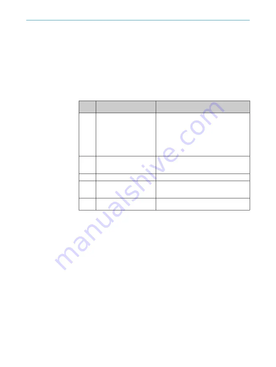
Scope of delivery

No. of
units

Component

Note

1

Device in the version ordered

Camera housing with C-mount threaded connec‐
tion

Order individual components separately as
accessories and mount them independently.

Light inlet is sealed with a protective cap.

Electrical connections are sealed with protective
caps.

Without holders and connecting cables

2

Sliding nut, 5.5 mm deep, with
M5 threaded fixing hole

Alternative mounting option for the device
instead of the threaded mounting hole

Use in pairs.

1

Hexagon key WAF 2

For mounting the integrated VI83I illumination unit

1

LED warning label RG 2 (self-
adhesive)

The LED warning label is included in the scope of
delivery of the separately-ordered RG 2 illumination
unit.

1

Printed safety notes, multilin‐
gual

Brief information and general safety notes

With special variants, where optional extras have been ordered, or owing to the latest
technical changes, the actual scope of delivery may vary from the features and illustra‐
tions shown here.

3.3

Product ID

3.3.1

Type label

The type label contains information for identifying the product.

PRODUCT DESCRIPTION

14

O P E R A T I N G   I N S T R U C T I O N S | Lector85x Flex

8027859//2022-06-22 | SICK

Subject to change without notice

Summary of Contents for Lector85 Flex Series

Page 1: ...O P E R A T I N G I N S T R U C T I O N S Lector85x Flex Image based code reader ...

Page 2: ...issible within the limits of the legal determination of Copyright Law Any modi fication abridgment or translation of this document is prohibited without the express written permission of SICK AG The trademarks stated in this document are the property of their respective owner SICK AG All rights reserved Original document This document is an original document of SICK AG 2 O P E R A T I N G I N S T ...

Page 3: ...arning label 12 2 9 Applying the LED warning label 13 3 Product description 14 3 1 Product variants 14 3 2 Scope of delivery 14 3 3 Product ID 14 3 3 1 Type label 14 3 3 2 Type code 15 3 4 Setup and dimensions 16 3 5 Integrated illumination unit 17 3 6 Display and control elements 17 4 Transport and storage 19 4 1 Transport 19 4 2 Unpacking 19 4 3 Transport inspection 19 4 4 Storage 19 5 Mounting ...

Page 4: ...figuration data 36 7 4 Installing firmware updates 36 8 Maintenance 37 8 1 Maintenance plan 37 8 2 Cleaning 37 9 Troubleshooting 39 9 1 General faults warnings and errors 39 9 2 Diagnostics using SOPASair 39 9 2 1 Error log 39 9 2 2 Diagnostic file 39 9 3 Repairs 39 9 4 Returns 39 9 5 Disassembling the device 40 9 6 Replacing the device 40 9 6 1 Transferring configuration data 40 9 6 2 Putting the...

Page 5: ... Annex 47 12 1 Declarations of conformity and certificates 47 12 2 Licenses 47 CONTENTS 8027859 2022 06 22 SICK O P E R A T I N G I N S T R U C T I O N S Lector85x Flex 5 Subject to change without notice ...

Page 6: ...dling and safe operation of the machine or system in which the device is integrated Information on this can be found in the operating instructions for the machine or system 1 2 Explanation of symbols Warnings and important information in this document are labeled with symbols Sig nal words introduce the instructions and indicate the extent of the hazard To avoid accidents damage and personal injur...

Page 7: ...rovided depending on the product such as Model specific online data sheets for device types containing technical data dimensional drawing and specification diagrams Declarations of conformity and certificates of the product family Dimensional drawings and 3D CAD dimension models of the device types in various electronic formats Other publications related to the devices described here Publications ...

Page 8: ...uirements must be met If these requirements are not met the device does not fulfill any specified enclosure rating The cables plugged into the electrical connections must be screwed tight Any electrical connections that are not being used must be sealed with a tightly fastened protective cap as in the delivery condition The cover on the top of the device is closed The optics protection hood must b...

Page 9: ...otection against cybersecurity threats if the product is used as part of such a concept You will find further information at www sick com psirt e g General information on cybersecurity Contact option for reporting vulnerabilities Information on known vulnerabilities security advisories 2 4 Limitation of liability Relevant standards and regulations the latest technological developments and our many...

Page 10: ... design and setup of the described connections and interfaces Basic knowledge of data transmission Basic knowledge of 1D technology bar code or 2D technology matrix code Operation of the device for the particular application Knowledge of the operation and control of the devices in their particular application Knowledge of the software and hardware environment for the particular application 2 7 Ope...

Page 11: ...tical radiation Class 1 Laser Product The accessible radiation does not pose a danger when viewed directly for up to 100 seconds It may pose a danger to the eyes and skin in the event of incorrect use Do not open the housing Opening the housing may increase the level of risk Current national regulations regarding laser protection must be observed Caution Use of controls or adjustments or performan...

Page 12: ...l systems must only be performed by qualified electricians Follow the notes in the operating instructions Install the grounding for the product and the system in accordance with national and regional regulations 2 8 LED warning label Illumination unit Illumination units with LEDs in risk group RG2 are provided with a warning label Figure 1 Risk Group RG2 CAUTION Possibly hazardous optical radiatio...

Page 13: ...d of the device in a well visible location Approach 1 Attach the illumination unit to the housing of the device 2 Manually adjust the sharpness and aperture of the lens unit Check the adjust ment using SOPASair 3 Attach the optics protection hood and screw it tight 4 Apply the warning label to the optics protection hood in a well visible location near the light outlet 5 If the device itself is for...

Page 14: ...ables 2 Sliding nut 5 5 mm deep with M5 threaded fixing hole Alternative mounting option for the device instead of the threaded mounting hole Use in pairs 1 Hexagon key WAF 2 For mounting the integrated VI83I illumination unit 1 LED warning label RG 2 self adhesive The LED warning label is included in the scope of delivery of the separately ordered RG 2 illumination unit 1 Printed safety notes mul...

Page 15: ...9 Scan me ß QR code with a link to the product and more information 3 3 2 Type code The devices of the product family are arranged according to the following type code V2D 8 5 aa b c d e f g h i j w l 1 3 4 5 6 7 8 9 10 11 12 13 14 15 16 17 18 19 Position Description Characteristic 1 3 Device name type V2D Vision 2D matrix 4 Product family 8 8xx series 5 Platform housing 5 Advanced Line 6 7 Image ...

Page 16: ... 4 02 22 2 0 87 13 6 0 54 97 8 3 85 15 9 0 55 143 4 5 65 min 8 0 31 max 87 3 43 Figure 4 structure and device dimensions unit mm inch decimal separator period 1 Optics protection hood accessory 2 USB 3 MicroSD memory card 4 4 tapped blind holes M2 5 5 5 mm deep for mounting the spacer 5 C mount thread 6 Cover service 7 Two M5 sliding nuts 5 5 mm deep pivoting as an alternative method of mounting t...

Page 17: ...ation software With the default device settings for example the green feedback LED briefly produces a green light spot within the field of view of the device after a successful read Laser alignment aid not available The laser alignment aid produces a red cross in the field of view of the object The alignment aid can be switched off 3 6 Display and control elements Overview 1 1 Status LEDs Status L...

Page 18: ...Green Data transmission over the network 10 100 MB s O Blue Connected to network 1 GB s Ö Blue Data transmission over the network 1 GB s o off O illuminated Ö flashing 3 PRODUCT DESCRIPTION 18 O P E R A T I N G I N S T R U C T I O N S Lector85x Flex 8027859 2022 06 22 SICK Subject to change without notice ...

Page 19: ...cept the delivery or only do so conditionally Note the scope of damage on the transport documents or on the transport compa ny s delivery note File a complaint NOTE Complaints regarding defects should be filed as soon as these are detected Damage claims are only valid before the applicable complaint deadlines 4 4 Storage Store the device under the following conditions Recommendation Use the origin...

Page 20: ...ounted lens e g for removal of a device that is not switched on and where the ambient temperature is above 35 C 5 2 Preparation for mounting 5 2 1 Installation requirements Mounting requirements Typical space requirement see type specific dimensional drawing Comply with the technical data such as the permitted ambient conditions for operation see Technical data page 42 Only mount the device using ...

Page 21: ...ance and field of view size 1 3 2 1 Working distance 2 Depth of field 3 Field of view size horizontal x vertical mm in working distance 1 The perceived field of view area is determined by the focus position the focal length of the lens and the working distance The necessary working distance can be determined from the field of view diagram Focus setting The focus position can be adjusted manually o...

Page 22: ...f view diagrams Lector85x Flex H x V mm 1 0 Working distance and focus position in mm 2 500 x 367 1000 x 734 2000 x 1469 2500 x 1836 1500 x 1069 f 12 mm f 16 mm f 25 mm 0 500 1000 1 500 2 000 2 500 3 000 1 Perceived field of view area horizontal x vertical mm 2 Working distance and focus position in mm 5 MOUNTING 22 O P E R A T I N G I N S T R U C T I O N S Lector85x Flex 8027859 2022 06 22 SICK S...

Page 23: ...short 6 Integratable illumination unit 7 Spacer right 8 Light inlet with threaded connection for lens Important information CAUTION Risk of injury due to hot device surface The surface of the device can become hot during operation Before performing work on the device e g mounting cleaning disassembly switch off the device and allow it to cool down Ensure good dissipation of excess heat from the de...

Page 24: ...ch for 65 Ncm Approach 1 Switch off the supply voltage to the device 2 Peel off the white protective sticker on the camera housing that covers the electri cal connection for the ring illumination unit 3 Place the camera housing on a nonslip base 4 Remove the protective cap from the round light inlet 5 Carefully insert the optional filter and spacer disk into the light inlet 6 Screw the lens unit i...

Page 25: ...tely ordered optional SICK mounting system using the slid ing nuts on the device 2 Align the device taking into consideration the field of view and the application circumstances 3 Connect the device to interfaces and supply voltage when disconnected from voltage The Ready status LED lights up green 4 Perform fine adjustment Further topics Mounting systems are available as accessories Accessories M...

Page 26: ...ntrol Wire cross sections in the supply cable from the customer s power system must be implemented in accordance with the applicable standards In the case of open end cables make sure that bare wire ends do not touch Wires must be appropriately insulated from each other 6 1 1 Data cables Important information NOTE Layout of data cables Use screened data cables with twisted pair wires Implement the...

Page 27: ...any local trigger sensor s system controller via shielded cables The cable shield for the data cable for example rests against the metal housing of the device The device can be grounded through the cable shield or through a blind tapped hole in the housing for example If the peripheral devices have metal housings and the cable shields are also in contact with their housings it is assumed that all ...

Page 28: ... widely distributed system installations On widely distributed system installations with correspondingly large potential differen ces the setting up of local islands and connecting them using commercially available electro optical signal isolators is recommended This measure achieves a high degree of resistance to electromagnetic interference Electro optical signal isolator Electro optical signal ...

Page 29: ... 7 Ground potential difference 8 Grounding point 1 9 Metal housing ß Shielded electrical cable Even in the event of large differences in the ground potential ground loops are effec tively prevented As a result equalizing currents can no longer flow via the cable shields and metal housing NOTICE The voltage supply for the device and the connected peripheral devices must also guarantee the required ...

Page 30: ...CAN H 5 TD RS 422 Host Do not connect 6 TD RS 422 Host TxD RS 232 host Do not connect 7 TxD RS 232 Aux Do not connect 8 RxD RS 232 Aux Do not connect 9 SensGND Do not connect 10 Sensor 1 digital input Do not connect 11 RD RS 422 Host Do not connect 12 RD RS 422 host RxD RS 232 host Do not connect 13 Result 1 digital output Do not connect 14 Result 2 digital output Do not connect 15 Sensor 2 digita...

Page 31: ...nformation on interfaces Technical data 6 4 Connecting the device 6 4 1 Electrically connecting the device Important information NOTICE Observe the wiring instructions see Wiring instructions page 26 Approach 1 Ensure the voltage supply is not connected 2 Connect the device according to the connection diagram Further topics Connections and pin assignment ELECTRICAL INSTALLATION 6 8027859 2022 06 2...

Page 32: ...n The devices communicate with each other and are supplied with voltage via the CAN interface A maximum of 3 devices can be connected in series line topology The devices are connected via a Y cable For a CAN network with more than 3 devices a separate voltage supply must be used for every 3 devices Communication between all devices in the network is done via CAN Complementary information Informati...

Page 33: ...put parameterization 9 CAN Power increment trigger focus code ß CAN male connector with terminating resistor Connection to 6 devices X1 X2 P3 P1 P2 P1 P2 P1 P2 P1 P2 P1 P2 P1 P2 X1 X2 P3 X1 X2 P3 X1 X2 P3 X1 X2 P3 X1 X2 P3 SOPAS SOPAS 1 2 9 7 8 3 4 6 5 Switsh T4A Ethernet Gbit ß CAN MSC800 Track Trace Controller MSC800 Track Trace Controller Fuse Block Fuse Block àCAN Figure 14 Connection principl...

Page 34: ...Ethernet Image output parameterization ß CAN Power increment trigger focus code à CAN male connector with terminating resistor 6 ELECTRICAL INSTALLATION 34 O P E R A T I N G I N S T R U C T I O N S Lector85x Flex 8027859 2022 06 22 SICK Subject to change without notice ...

Page 35: ... used to permanently save the parameters The saved parameters can be manually saved imported and exported as a project file on the computer in the SOPAS ET configuration software Prerequisites Computer with the SOPAS ET software installed The most up to date version of the SOPAS ET software can be downloaded from www sick com SOPAS_ET The respective system requirements for installing SOPAS ET are ...

Page 36: ...To be able to restore the parameter set to a replacement device if required e g device failure you should also save the configuration data externally Approach 1 Permanently saving the parameters in SOPASair The device stores the parameter set internally in the permanent parameter mem ory 2 Open SOPAS ET 3 In SOPAS ET manually save the parameter set as a project file on the computer The parameter s...

Page 37: ...ds on ambient conditions and climate Recommended At least every 6 months Specialist 8 2 Cleaning Cleaning includes the viewing window and the housing of the device NOTICE Equipment damage due to improper cleaning Improper cleaning may result in equipment damage Only use recommended cleaning agents and tools Never use sharp objects for cleaning Cleaning the viewing window Check the viewing window o...

Page 38: ...ypes It is not possible to entirely rule out temporary disorienting optical effects particularly in conditions of dim lighting Disorienting optical effects may come in the form of dazzle flash blindness afterimages photosensitive epilepsy or impairment of color vision for example b Switch off the device for the duration of the cleaning operation If this is not possible wear suitable laser safety g...

Page 39: ...y Operation Start stop operation external read cycle missing more than one object is in the reading field Device faults hardware software 9 2 Diagnostics using SOPASair 9 2 1 Error log The error log contains current error messages 9 2 2 Diagnostic file You can create and download a diagnostic file in the configuration software for service purposes The diagnostic file contains data required for fau...

Page 40: ...t device of the same device type Project file with current configuration data Approach b Transfer the configuration data via download to the replacement device and save it there permanently Further topics Saving the configuration data 9 6 2 Putting the replacement device into operation Approach 1 Mount and align the replacement device When doing so note the previously applied markings on the brack...

Page 41: ...ance with the applicable country specific waste disposal regulations Do not dispose of the product along with household waste NOTICE Danger to the environment due to improper disposal of the device Disposing of devices improperly may cause damage to the environment Therefore observe the following information Always observe the national regulations on environmental protection Separate the recyclabl...

Page 42: ... integratable VI83I ring illumination unit 1 LED Visible green light λ 525 nm 15 nm RG 1 LED risk group of illumination unit Variants of the integratable VI83I ring illumination unit risk group RG 2 Type visible white light medium and feedback LED part number 2125084 Type visible white light wide and feedback LED part number 2125085 Risk group 2 moderate risk according to IEC 62471 1 2006 07 EN 62...

Page 43: ...ng window material Glass or plastic PMMA 2 mm thick with scratch proof coating see Type code page 15 Cover top of device Material Plastic Function For temporary access to the microSD memory card slot and the USB connection Hinged 3 screws SW2 hexagon key captive Enclosure rating IP 65 IEC 60529 2013 C1 2013 C2 2015 AMD2 C1 2019 EN 60529 1991 A1 2010 A2 2013 AC 2019 02 4 Electrical safety EN 61010 ...

Page 44: ...smission rate 10 100 1 000 Mbit s MAC address device specific see type label CAN Protocol SICK CAN sensor network CSN slave Function Host data output of the read result Data transmission rate 500 kbit s USB 2 0 No function Reading pulse CAN Optical displays 10 status LEDs 2 feedback LEDs of the integratable VIxxx ring illumination unit green red Operator interfa ces Web server Configuration softwa...

Page 45: ...re 0 C 50 C 1 Storage tempera ture 20 C 70 C Permissible rela tive humidity 0 90 non condensing Ambient light immunity 2 000 lx on code Ambient condi tions Degree of contamination 2 according to EN 61010 1 Altitude 5 000 m above sea level 1 If the ambient operating temperature will be 45 C ensure adequate heat dissipation when mounting the device see Mounting instructions page 20 TECHNICAL DATA 10...

Page 46: ...essories and if applicable mounting information can be found online at www sick com Lector85x 11 ACCESSORIES 46 O P E R A T I N G I N S T R U C T I O N S Lector85x Flex 8027859 2022 06 22 SICK Subject to change without notice ...

Page 47: ...ral Public License LGPL MIT license zlib license and licenses derived from the BSD license This program is provided for general use without warranty of any kind This warranty disclaimer also extends to the implicit assurance of marketability or suitability of the program for a particular purpose More details can be found in the GNU General Public License For license texts see www sick com licenset...

Page 48: ...co Phone 52 472 748 9451 E Mail mexico sick com Netherlands Phone 31 0 30 229 25 44 E Mail info sick nl New Zealand Phone 64 9 415 0459 0800 222 278 tollfree E Mail sales sick co nz Norway Phone 47 67 81 50 00 E Mail sick sick no Poland Phone 48 22 539 41 00 E Mail info sick pl Romania Phone 40 356 17 11 20 E Mail office sick ro Russia Phone 7 495 283 09 90 E Mail info sick ru Singapore Phone 65 6...

Reviews: