6.4.2
Connecting the supply voltage
Prerequisites
•
The voltage source meets the requirements of ES1 (EN 62368-1) or SELV
(EN 60950-1).
•
Required power output of the voltage source: at least 48 W
•
To ensure protection against short-circuits/overload in the customer’s supply
cables, choose and implement wire cross-sections in accordance with the appli‐
cable standards.
Observe applicable standards (Germany):
°
DIN VDE 0100 (part 430)
°
DIN VDE 0298 (part 4) and DIN VDE 0891 (part 1)
Approach
Protect the device with an external fuse
b
For a supply voltage of DC 24 V ± 20%, protect the device using a separate fuse
rated at 2 A. Install the fuse in the supply circuit at the start of the supply cable.
6.4.3
CAN interface
Configuration of the CAN interface
Configure the CAN data interface using SOPASair.
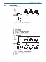
Series connection
The devices communicate with each other and are supplied with voltage via the CAN
interface. A maximum of 3 devices can be connected in series (line topology). The
devices are connected via a Y-cable.
For a CAN network with more than 3 devices, a separate voltage supply must be used
for every 3 devices. Communication between all devices in the network is done via CAN.
Complementary information
Information on using the device in conjunction with a modular system controller or a
Sensor Integration Machine can be found in the associated publications. The publica‐
tions can be found at sick.com/{part number}.
Publications
•
MSC800 Modular System Controller operating instructions, part number 8011539
•
SIM2000ST Sensor Integration Machine operating instructions, part number
8020763
•
SIM2000ST-E Sensor Integration Machine operating instructions, part number
8025453
6
ELECTRICAL INSTALLATION
32
O P E R A T I N G I N S T R U C T I O N S | Lector85x Flex
8027859//2022-06-22 | SICK
Subject to change without notice


