Table 6: Bore hole depth of piston rode and installation cavity for electrical connection
Null zone
MAX48: 30.0 mm
MAX30: 21.5 mm
Measuring range
As per the applicable data sheet and selected
device variant
Damping
NOTE
The total bore hole depth comprises the measuring range
1
, the
damping
2
, and
an
addition distance of 3 mm to the pressure pipe. Bore hole diameter (d) in the piston
(depending on type).
4.4
Encoder installation
1
2
1
Support ring
2
O-ring
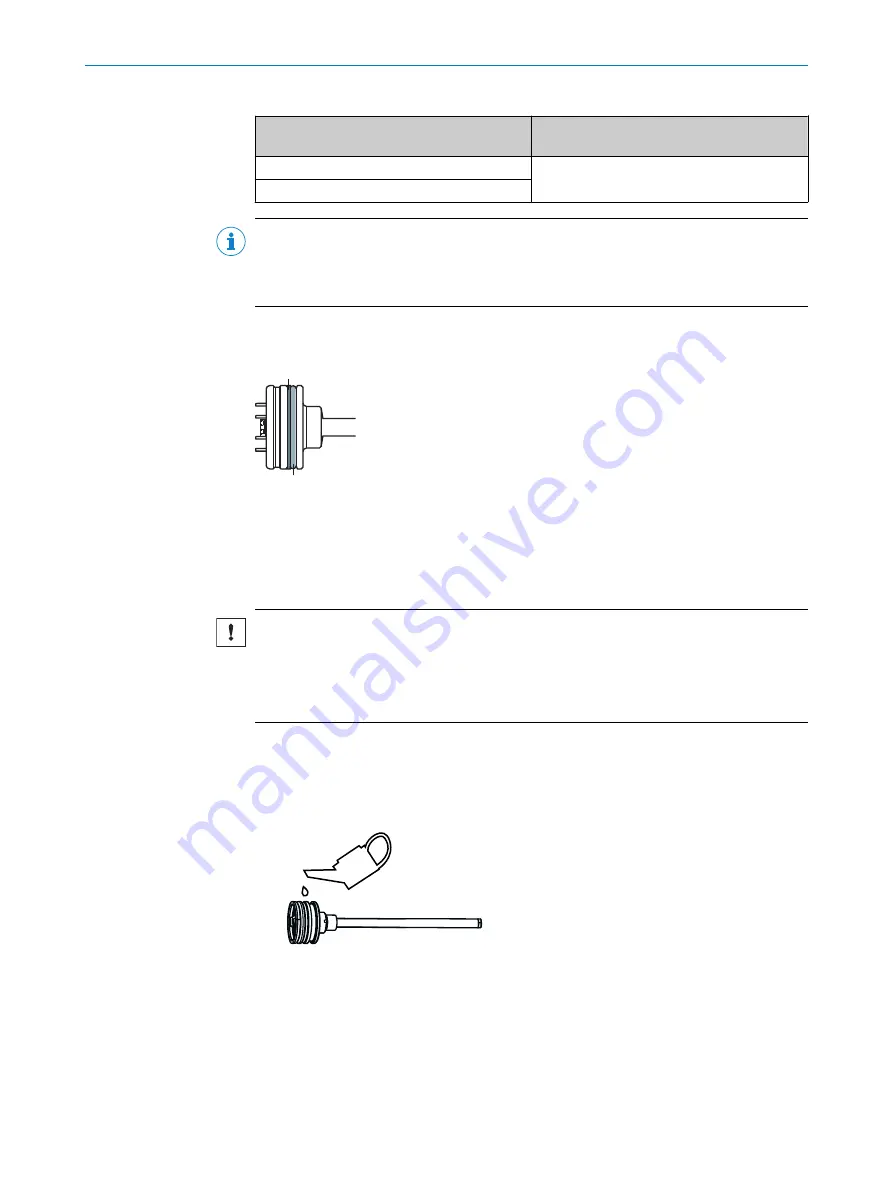
The O-ring and support ring are pre-installed as shown in the figure and prevent oil from
penetrating into the connector area.
NOTICE
Risk of damage to the connecting cables during mounting.
Tensile loads and sharp edges can damage the strands and connecting cables of the
male connector system.
Avoid tensile loads and look out for sharp edges when mounting the connector system.
4.4.1
Mounting in the cylinder
4.4.1.1
Insertion in the cylinder
1.
Lubricate the O-ring, support ring and pressure pipe.
2.
Carefully insert the encoder into the cylinder.
3.
Guide the connecting cable carefully through the cylinder wall (bore hole).
4
MOUNTING
24
O P E R A T I N G I N S T R U C T I O N S | MAX
®
8022793/1EFT/2021-12-15
| SICK
Subject to change without notice


