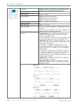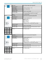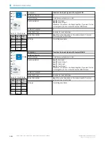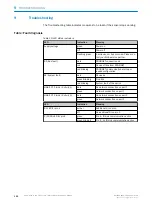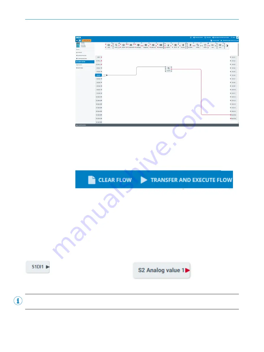
Download new Logic to the Device
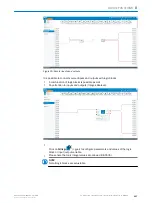
Figure 32: Transfer and execute flow
Press
Tansfer and Execute Flow
to synchronize your workflow with your device. All changes
you made without pressing this button will be lost and are not downloaded to your
SIG200 device.
8.2.1
Deleting the Logic from the Device
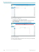
Press CLEAR FLOW to delete the complete logic from the configuration window. Note
that you need to press TRANSFER AND EXECUTE FLOW to also delete the logic from the
actual device.
8.2.2
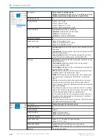
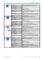
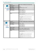
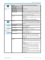
Explanation of Inputs, Outputs and Logic Blocks
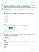
IO-Link Ports
The logic editor visualizes, in case an IODD for the device has been uploaded, the process data as they are defined
within the IODD of the IO-Link device. Inputs are displayed on the left side, outputs are visualized on the right side
of the logic editor workspace. So, the logic editor view is depending on the connected IO-Link devices.
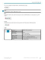
Example: If you connect e.g. an inductive proximity sensor IMC on port S1 of SIG200, the input side looks like this:
With a red triangle, an integer value is symbolized. With a black triangle, a boolean variable is identified.
NOTE
Last valid process data value is provided in case of a IO-Link connection loss to the connected device.
DEVICE FUNCTIONS
8
8017853.1D0S/2021-11-04 | SICK
O P E R A T I N G I N S T R U C T I O N | Sensor Integration Gateway - SIG200
109
Subject to change without notice

