6
Electrical installation
The SIG200 power and IO-Link cables must be connected in a voltage-free state (U
V
=
0 V). The following information must be observed, depending on the connection type:
Even if the wiring is looped through, the total current of the module must not exceed
3 A.
NOTICE DAMAGE OF EQUIPMENT
Equipment damage due to incorrect supply voltage! Please note the instructions for
electrical installation.
An incorrect supply voltage may result in damage to the equipment. Operation in
short-circuit protected network max. 8 A is allowed.
Only apply voltage/switch on the voltage supply (U
V
> 0 V) once all electrical connec‐
tions have been established.
Male and female connectors that are not used must be sealed with blind caps so that
the enclosure rating of IP 67 is assured.
Explanation of the connection diagrams:
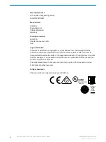
DI = Digital input
DO = Digital output
FE = functional ground
IO-Link = IO-Link communication (C)
n. c. = not connected
Rx+ = Re
Rx- = Receiver -
Tx+ = Trans
Tx- = Trans
6.1
Pin alignment
U
B
: 10 ... 30 V DC
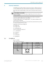
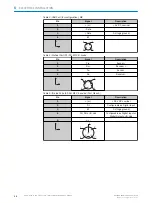
Table 2: Power Port, M12 A-coded
Pin
Signal
Description
1
+ (L+)
+ 24 V DC nominal
2
n.c.
not connected
3
M
0 V
4
n.c.
not connected
1
2
4
3
I
N
= 4 A
ELECTRICAL INSTALLATION
6
8017853.1D0S/2021-11-04 | SICK
O P E R A T I N G I N S T R U C T I O N | Sensor Integration Gateway - SIG200
11
Subject to change without notice


