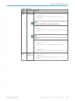
NOTE
Be aware that the current configuration is deleted and replaced with the new configura‐
tion from the IO-Link device.
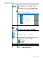
Download / Import / Export:
Export
and
Import
allow you to copy the contents of a port data storage container from
one SIG200 to a second SIG200. Once the contents of the data memory have been
imported into the second SIG200, they can be downloaded to the connected IO-Link
device.
NOTE
If the individual underside for the ports remains empty, then either no IO-Link device is
physically connected to the SIG200 or the connected device is not an IO-Link device.
7.3.6
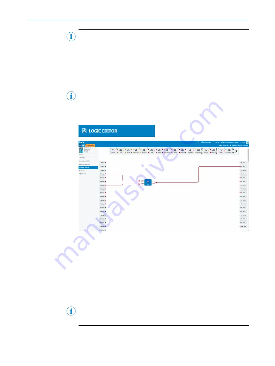
LOGIC EDITOR
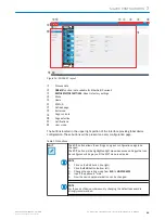
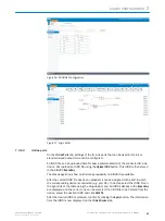
page (logic editor)
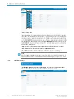
Figure 20:
LOGIC EDITOR
page (logic editor)
The
LOGIC EDITOR
page of SIG200 allows you to apply user-defined logic functions to the
available input signals and transmit the results to various output signals by dragging
and dropping logic blocks and connection cables.
The left side of the screen lists all configured inputs. The upper middle bar contains the
available logic gates that can be dragged down into the workspace. And listed on the
right side are the configured outputs.
Before setting up any logic, it is required to upload the relevant IODD files. This ensures
that the correct inputs and outputs of every connected IO-Link device are displayed
correctly.
NOTE
Note that the screen is grayed out until you change to editing mode (
Creating a logic system
1.
To select the desired logic blocks, click and drag them to the working range.
SIG200 CONFIGURATION
7
8017853.1D0S/2021-11-04 | SICK
O P E R A T I N G I N S T R U C T I O N | Sensor Integration Gateway - SIG200
57
Subject to change without notice

