ß
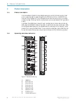
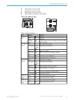
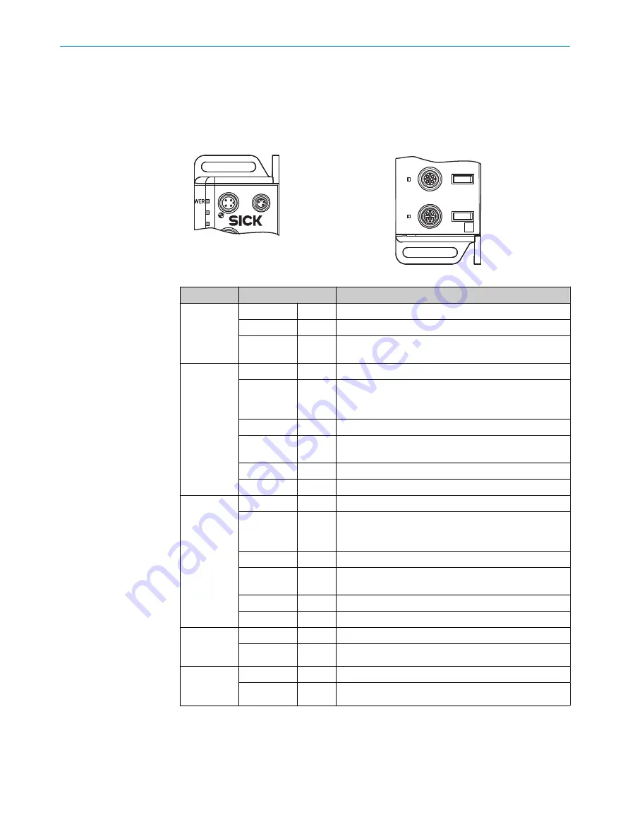
Mounting hole for front mounting
à
Mounting hole for side mounting
á
Removable user defined port labels
â
USB Port (M8) for configuration with SOPAS ET
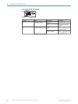
LEDs on the fieldbus module
SF
BF
SIG200
POWER
CONFIG
1
2
3
LINK
ACT2
LINK
ACT1
P2
P1
Table 1: LED status indicators
LED
Display
Meaning
Supply volt‐
age
green
O
Power on
Off
o
Power off
Flashing
green
Ö
A serious error has occurred. Please contact your SICK
service partner.
MS (Module
status)
dark
o
The module has no power
red / green
alter‐
nately
Ö
Self-test when switching on
green
O
Device in operation
green blink‐
ing
Ö
Device in standby, no IP address assigned
red
O
Error (device not in operation)
red blinking
Ö
Warning (but device in operation)
NS (Network
status)
dark
o
No voltage or IP address
red / green
alter‐
nately
Ö
Self-test when switching on
green
O
Valid IP address and CIP connection
green blink‐
ing
Ö
Valid IP address, no connection
red
O
IP address assigned to a different device
red blinking
Ö
Connection timeout
LINK ACT 1
(Link / Activ‐
ity 1)
dark
o
No network connection on port 1
green
O
Network connection on port 1
LINK ACT 2
(Link / Activ‐
ity 2)
dark
o
No network connection on port 2
green
O
Network connection on port 2
PRODUCT DESCRIPTION
3
8017853.1D0S/2021-11-04 | SICK
O P E R A T I N G I N S T R U C T I O N | Sensor Integration Gateway - SIG200
7
Subject to change without notice


