background image

9.5

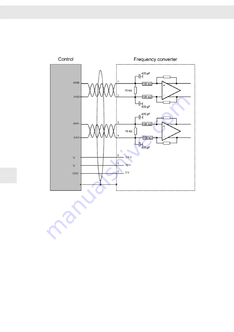
X29 – Analog Inputs/Outputs

9.5.1

Analog inputs

Connection Examples

W

52

FC2 - Frequency converter 02192100xy

9

Summary of Contents for FC2

Page 1: ...FC2 Frequency converter 02192100xy Hardware Description P TD 0000552 2 2019 08 26 SIEB MEYER W ...

Page 2: ...YER AG Auf dem Schmaarkamp 21 21339 Lueneburg Germany Phone 49 4131 203 0 Fax 49 4131 203 2000 support sieb meyer de http www sieb meyer de SIEB MEYER Shenzhen Trading Co Ltd Room A208 2 F Internet Innovation and Creation services base Building 2 No 126 Wanxia road Shekou Nanshan district Shenzhen City 518067 China Phone 86 755 2681 1417 86 755 2681 2487 Fax 86 755 2681 2967 sm_china_support1 163 ...

Page 3: ...ng EMC 4 Description of the Device 5 Device View and Dimensions 6 Technical Data 7 Connectors 8 Connection Examples 9 Initial Operation 10 Status Display and Error Messages 11 Safety Circuit Restart Lock STO 12 Appendix 13 Index 14 W Chapter Overview FC2 Frequency converter 02192100xy 3 ...

Page 4: ...Chapter Overview W 4 FC2 Frequency converter 02192100xy ...

Page 5: ...f Line and Field Interferences According to Category C3 21 5 Description of the Device 23 5 1 Fields of Application 23 5 2 Features of the Series FC2 23 5 3 Type Plate 24 5 4 Function 25 5 4 1 General Functional Description 25 5 4 2 Working Method of the System 25 6 Device View and Dimensions 27 6 1 View Ventilation 27 6 2 Dimensions 28 7 Technical Data 29 8 Connectors 31 8 1 ID Switch 32 8 2 X1 X...

Page 6: ...with OSSD 51 9 3 2 Wiring without OSSD 51 9 4 X26 X27 SERVOLINK 51 9 5 X29 Analog Inputs Outputs 52 9 5 1 Analog inputs 52 9 5 2 Analog Outputs 53 9 6 X30 Digital Inputs Outputs 53 9 6 1 Digital Inputs 53 9 6 2 Digital Outputs 54 9 7 X31A B Speed Sensor and Motor Temperature Sensor 54 9 7 1 Speed Sensor 54 9 7 2 Motor Temperature Sensor 55 9 8 X32 Inputs for Spindle Selection 55 9 9 X33 Outputs fo...

Page 7: ...2 3 Requirements and Standards 68 13 Appendix 71 13 A Manufacturers 71 13 A 1 SIEB MEYER Accessories 71 13 A 1 1 Connectors of the Series FC2 71 13 A 1 2 Line Filters by TDK EPCOS Group 71 13 A 2 Phoenix Contact 72 13 A 3 TOSHIBA Fiber Optic Connectors 72 14 Index 73 W Content FC2 Frequency converter 02192100xy 7 ...

Page 8: ...Content W 8 FC2 Frequency converter 02192100xy ...

Page 9: ...Risk symbol Graphic representation of the source of risk Risk levels Risk Level Description Indicates an imminently hazardous situation which if not avoided will result in death or serious injury Indicates a potentially hazardous situation which if not avoided could result in death or serious injury Indicates a potentially hazardous situation which if not avoided may result in minor or moderate in...

Page 10: ...ostatically sensitive components Risk of property damage 1 2 Illustration of General Notices Symbol Description Hint with additional further information Tip with suggestions and useful information 1 3 Abbreviations n c not connected STO safety function Safe Torque Off VCC voltage at the common collector About this Manual W 10 FC2 Frequency converter 02192100xy 1 ...

Page 11: ...k This manual has the following demands on the trained staff of machine manufacturers Transport only by skilled employees familiar with handling electrostatically sensitive components Installation only by experts with electromechanical experience Initial operation only by experts with experience in the fields of electrical engi neering drive technology Information concerning the initial operation ...

Page 12: ...General Information W 12 FC2 Frequency converter 02192100xy 2 ...

Page 13: ...ion confirms the CE conformity of the complete machine or installation If the mechanics or the electronics of the device are modified the conformity with the EC EEC directives and thus the label will expire 3 2 Working on the Device WARNING Trained staff only To avoid risks of serious injuries and material damage any works regarding instal lation initial operation and maintenance must be carried o...

Page 14: ...onductive impurities and humidity during the operation SIEB MEYER products are not suitable for use in areas exposed to explosion hazards ATEX zones without approriate housing Terms according to DIN EN 61800 Before initial operation make sure that the machine will not expose danger e g runaway moves The conformity with the safety standards DIN EN 60204 1 and DIN EN 61800 5 1 must be ensured The ma...

Page 15: ...r to the product documentation of your device to find out whether or not your device is equipped with a line filter For detailed information on line filters refer to the manual EMC Guidelines 3 4 Reasonably Foreseeable Misuse The Machinery Directive defines a reasonably foreseeable misuse as use of machi nery in a way not intended in the instructions but which may result from predictable human beh...

Page 16: ...istor for one hour Please contact the SIEB MEYER service department for details 3 6 Installation NOTICE Damage of electrostatically sensitive components due to improper handling Never touch electronic components Consider specific mounting instructions for your device Mechanical installation conditions for the system according to DIN EN 61800 2 Vibrations must remain within the limit values of the ...

Page 17: ... chloride Make sure that the aeration elements are free and open so that the air circulation is not restricted 3 7 Electrical Connection DANGER Risk of serious injuries due to touch voltages After electric devices have been switched off touch voltages may occur depending on the device up to 4 minutes Longer construction related discharge times are possible Refer to the product documentation of you...

Page 18: ...rters Prevent cable loops Therefore the units must only be connected to earth at the provided PE connection for the mains supply line and the racks only at the provided earth screw DANGER Connection of the power supply unit This product may cause touch current in the protective earthing conductor The current in the protective earthing conductor can exceed 3 5 mA AC or 10 mA DC Pay attention to the...

Page 19: ...ons e g law about technical material rules for prevention of accidents etc 3 9 Maintenance The unit must be checked regularly for cleanness and functionality depending on the ambient pollution This applies in particular for installed fans 3 10 Disposal Make sure to consider country specific waste and disposal laws and statutes for the disposal of packing material used batteries and irreparable dev...

Page 20: ...elec tricians without license when the device has been employed although the protection equipment was defective when the maximum permissible input voltage has been exceeded due to improper operation when the device or its equipment have been modified when the device was affected by foreign material or force majeure NOTICE Due diligence of the machine manufacturer A first programming carried out by...

Page 21: ...les longer than 5 m are used an external line filter may be required For detailed information on mounting and connecting line filters refer to the manual Unit Assembly complying EMC If no internal line filter is provided an external line filter must be used to reach the category C3 NOTICE Connection of line filters Consider the connection instructions of the line filter manufacturer to ensure suff...

Page 22: ...Unit Assembly Complying EMC W 22 FC2 Frequency converter 02192100xy 4 ...

Page 23: ...with connectors at the front panel integrated power supply unit high motor efficiency very good concentricity by improved sine assessment of the motor current also during low speeds 2 independent motor data sets programmable load message externally set or firmly programmable threshold integrated protective functions electronic fuses for pulse shaped overload and short circuit electronic fuse for t...

Page 24: ...external power supply unit is necessary Rated current peak current Applies to the output stage indicated as RMS value Serial number Indicates the individual number of the device Device version Indicates the version of the hardware if no version is existent 0 000 is indicated here IP Code Indicates the level of protection of the device against touching or intrusion of solid objects 1st digit and wa...

Page 25: ...y converter transforms the inflexible mains supply into a rotating field continuously adjustable in voltage and frequency As a result the speeds are infinitely variable and the starting current is considerably reduced In addition suitable electronics permit compensation of parasitic characteristics of the motor or initiation of high dynamic control cycles In order to operate three phase motors at ...

Page 26: ...The frequency converter technology PAM described in this manual meets all require ments in the field of converter operated high speed motors and offers the advantage of loss minimization in the motor and frequency converter Pulse modulation methods PAM pulse amplitude modulation PWM pulse width modulation If a motor is decelerated faster than by natural friction losses the motor works as generator...

Page 27: ...he device is obstructed the device could overheat and possibly become damaged When installing the device pay attention to the direction of air flow through the internally installed fan arrows For sufficient cooling the ventilation inlets and outlets must be kept free by a space of min 10 cm W Device View and Dimensions FC2 Frequency converter 02192100xy 27 6 ...

Page 28: ...s of FC2 variant 02192100IF in mm inch The device is designed for vertical wall mounting Other setup positions are possible but you must consult SIEB MEYER before Device View and Dimensions W 28 FC2 Frequency converter 02192100xy 6 ...

Page 29: ...al ballast resistor Prated 400 W Ppulse for 1 s 13000 W Efficiency η about 0 95 Load cos φ 0 5 to 1 0 inductive Ambient temperature Θ 0 to 40 C Weight m 12 8 kg 1 The apparent output powers have been calculated for an output voltage of 220 Vrms 2 S1 continuous load with S1 values 3 S6 load that is alternating between 15 s of S6 values load and 12 s of 40 of S6 values open circuit operation W Techn...

Page 30: ...Technical Data W 30 FC2 Frequency converter 02192100xy 7 ...

Page 31: ...s Bus inputs page 33 X4 Bus Bus outputs page 33 X10 Safety Safety circuit restart lock STO page 33 X14 USB interface for parameter setting page 34 X26 SERVOLINK 4 optical input page 34 X27 SERVOLINK 4 optical output page 34 X29 Analog Analog inputs analog outputs page 36 X30 I O Digital inputs digital outputs page 38 X31A Feedback Speed sensor and motor temperature sensor of spindles 1 8 page 42 W...

Page 32: ...C D E F When the device is connected via SERVOLINK 4 only 12 addresses are available 0 to B The addresses of several devices in a system must be different from each other to ensure that they can be identified by the software 8 2 X1 X2 24V 4 pole Combicon connector suitable for mating connector MVSTBW 2 5 4 ST Phoenix X1 Name Meaning X2 Mating connector Pin I O I O Pin Mating connector 4 I 24 V Log...

Page 33: ...ound Related topics Connection examples X3 X4 Bus Connection page 49 8 4 X4 Bus Outputs Female RJ45 connector X4 Pin I O Name Meaning 1 O CAN_H CAN bus 2 O CAN_L CAN bus 3 I O D RS485 4 n c 5 n c 6 I O D RS485 7 I O GND Ground 8 I O GND Ground Related topics Connection examples X3 X4 Bus Connection page 49 8 5 X10 Safety STO Safety circuit and restart lock STO W Connectors FC2 Frequency converter ...

Page 34: ...n of terminal connections Conductor cross section solid stranded 0 14 to 1 5 mm Tightening torque 0 22 to 0 25 Nm The power supply unit is only activated when SAFEA and SAFEB are connected If the safety function STO is not required pin 1 and pin 3 must be bridged to pin 6 Related topics Connection example X10 Safety Circuit STO page 50 Safety function STO Safety Circuit Restart Lock STO page 65 8 ...

Page 35: ...eparation of Optical Fiber Cables with Connector Every optical fiber connector requires an optical fiber cable with a male connector The following information apply for connectors used in applications with 1 mm standard plastic optical fibers POF Technical data Rated value Storage temperature 40 to 70 C Operating temperature 20 to 70 C Tensile stress Between optical fiber cable and connector 19 6 ...

Page 36: ...ing residues You can order the following materials at SIEB MEYER Article SIEB MEYER article number Polishing disk for optical fiber cables 47000001 Dismantling tool for optical fiber cables 47000002 Grinding paper 47000003 8 8 X29 Analog Inputs Outputs 9 pole male submin D connector X29 Pin I O Name Meaning 1 I Reference value Differential amplifier input reference point for pin 2 2 I Reference va...

Page 37: ...generating external reference values Active load threshold The load message is equipped with a variable switching threshold This switching threshold can either be determined via the analog input Load or via program ming 8 8 2 Outputs There are two independent analog outputs provided programmable analog output 1 Programmable analog output 2 The following functions can be assigned to the outputs Tar...

Page 38: ...the heat sink Motor load The load of the motor is derived from the current 100 is the rated power at the oper ating point Power output stage load Load of the power output stage 100 is the peak power of the output stage at the operating point Power output stage voltage Voltage of the controlled intermediate circuit The voltage is directly proportional to the motor terminal voltage Load Currently ac...

Page 39: ...put 4 18 O OUT4 Programmable digital output 5 19 O OUT5 Programmable digital output 6 20 n c 21 n c 22 n c 23 I PTC0 Do not wire 24 O 24V 25 O 24V Stud bolt flange max tightening torque 0 7 Nm Related topics Connection examples X30 Digital Inputs Outputs page 53 8 9 1 Inputs Switch on When this input is activated the control of the frequency converter is connected to allow power transmission to th...

Page 40: ...d the like You can set the error reac tion as you desire it is coupled with the reaction to a mains failure 8 9 2 Outputs Speed pulse output The speed pulse output is conceived as complementary output That means the wanted signal is transmitted via one channel in this case UA and the inverted signal is transmitted via a second channel in this case UA Thus symmetric interferences do not influence t...

Page 41: ...re drivemaster2 Power output stage ready The internal closed loop control is activated and current is supplied to the spindle Target 0 If no rotating field is transmitted by the frequency converter Target 0 is signaled Real detection of the speed zero signal is possible when the speed sensor of the spindle is connected Target not 0 This is the inverted output of Target 0 Load message This output i...

Page 42: ...le 3 12 I PTC3 Motor temperature sensor of spindle 4 13 I PTC4 Motor temperature sensor of spindle 5 14 O VMEAS Supply voltage for the speed sensor 15 O VMEAS Supply voltage for the speed sensor 16 n c 17 O 12 V internal Internal voltage 12 V 18 I O Ground Reference ground 19 I O Ground Reference ground 20 I O Ground Reference ground 21 I O Ground Reference ground 22 I Ref sensor Reference voltage...

Page 43: ... n c 18 I O Ground Reference ground 19 I O Ground Reference ground 20 I O Ground Reference ground 21 I O Ground Reference ground 22 n c 23 n c 24 n c 25 n c Stud bolt flange max tightening torque 0 7 Nm Related topics Connection examples X31A B Speed Sensor and Motor Temperature Sensor page 54 8 10 3 Speed Sensor X31A B The speed sensor is not required for control operations The frequency converte...

Page 44: ...ge is saved and displayed The error message is acknowledged via the reset functions 8 11 X32 Inputs for Spindle Selection 15 pole female submin D connector X32 Pin I O Name Meaning 1 I SP1 Spindle 1 2 I SP2 Spindle 2 3 I SP3 Spindle 3 4 I SP4 Spindle 4 5 I SP5 Spindle 5 6 I SP6 Spindle 6 7 I SP7 Spindle 7 8 I SP8 Spindle 8 9 I SP9 Spindle 9 10 I SP10 Spindle 10 11 I SP11 Spindle 11 12 I SP12 Spind...

Page 45: ...election 11 17 O OUT19 Spindle selection 12 18 n c 19 n c 20 n c 21 n c 22 n c 23 n c 24 24 V_ext Voltage supply for outputs 25 24 V_ext Voltage supply for outputs Stud bolt flange max tightening torque 0 7 Nm The spindle selection is active when an input voltage of 24 V is applied When a spindle is selected the corresponding output at the connector X33 is set for feedback This output can be evalu...

Page 46: ...le lead through terminal with lever principle PLW 16 6 4 10 Phoenix X35 Name Meaning U Motor phase U V Motor phase V W Motor phase W Protective conductor Specification of terminal connections Conductor cross section solid 10 to 16 mm Conductor cross section stranded 10 to 25 mm Connection method push lock spring connection Related topics Connection example X35 Motor Phases page 56 General wiring i...

Page 47: ...smit data 2 O TX Transmit data 3 I RX Receive data 4 n c 5 n c 6 I RX Receive data 7 n c 8 n c Related topics Connection example X64 X65 EtherCAT page 58 Status of communication LED Status Display EtherCAT Connection page 61 W Connectors FC2 Frequency converter 02192100xy 47 8 ...

Page 48: ...Connectors W 48 FC2 Frequency converter 02192100xy 8 ...

Page 49: ...llowing sections provide connection examples for the individual connectors of the device 9 1 X1 X2 24 V Voltage supply 24 V 20 9 2 X3 X4 Bus Connection 9 2 1 RS232 Bus W Connection Examples FC2 Frequency converter 02192100xy 49 9 ...

Page 50: ...ing table indicates physical limitations valid for specific transmission rates Baud rate Max bus length 50 kBd 1000 m 125 kBd 500 m 250 kBd 250 m 500 kBd 100 m 1000 kBd 25 m The number of bus nodes is also limited by the specification according to ISO 11898 The limiting value is between 32 and 100 bus nodes depending on the used cable and transmission rate For further information on the maximum nu...

Page 51: ... 3 1 Wiring with OSSD OSSD Output Signal Switching Device 9 3 2 Wiring without OSSD OSSD Output Signal Switching Device 9 4 X26 X27 SERVOLINK W Connection Examples FC2 Frequency converter 02192100xy 51 9 ...

Page 52: ...9 5 X29 Analog Inputs Outputs 9 5 1 Analog inputs Connection Examples W 52 FC2 Frequency converter 02192100xy 9 ...

Page 53: ... Outputs 9 6 X30 Digital Inputs Outputs 9 6 1 Digital Inputs Signal State Input 0 V to 5 V L not active 10 V to 24 V H active 5 V to 10 V X not defined W Connection Examples FC2 Frequency converter 02192100xy 53 9 ...

Page 54: ...9 6 2 Digital Outputs 9 7 X31A B Speed Sensor and Motor Temperature Sensor 9 7 1 Speed Sensor Connection Examples W 54 FC2 Frequency converter 02192100xy 9 ...

Page 55: ...or Temperature Sensor 9 8 X32 Inputs for Spindle Selection signal State Input 0 V to 5 V L not active 10 V to 24 V H active 5 V to 10 V X not defined W Connection Examples FC2 Frequency converter 02192100xy 55 9 ...

Page 56: ...must be carried out with low impedance With respect to the ground connection one of the following actions must be done connect the motor housing to the ground of the machine or connect the ground terminal of the motor connector to the central ground point of the machine Consider the following with regard to shielding Always use shielded motor cables Related topics Chapter Motor Cable page 57 Conne...

Page 57: ...und loops and malfunction of the motor Connect the protective earth conductors additionally led in motor cables directly to the shield line and label them with T or PE If the procedure turns out to be impracticable omit the earth conductor connection in the motor cables and wire a separate earth conductor in parallel to the motor cables Ensure that the cable is returned to the drive Do not wire th...

Page 58: ...le length of the motor cable is 20 m 9 11 X64 X65 EtherCAT Ethernet connection cable To connect EtherCAT devices use only Ethernet cables of Category 5 Class D and higher You can either use patch cables 1 1 or crossover cables TX crosslinked to RX because the receiver ports PHY support automatic cable recognition auto crossover feature Connection Examples W 58 FC2 Frequency converter 02192100xy 9 ...

Page 59: ...rface and preventing pig tails in the wiring is especially advanta geous Connect the different components of the switch cabinet by star connection to one common ground point ground bar Wire power lines and sensor or logic lines in separately arranged cable channels 10 2 Connector Before starting the connection of the frequency converter ensure that it is mounted firmly and securely In particular c...

Page 60: ...The inputs for motor protection PTC and safety circuit are wired The logic supply 24 V is switched on The mains supply is switched on The frequency converter signals Ready for operation No error message was signaled If the described requirements are met the motor can be accelerated by means of the reference value when the function Start pulse enable is selected The acceleration time can be set Aft...

Page 61: ...e fast Pre operational Only SDO communication is possible No process data are transmitted The LED flashes at the following intervals slow Safe operational As process data only actual values are transmitted from the slave drive to the master SDO communication is possible The LED flashes at the following intervals Operational The complete data channel is active L2 error Red Communication error L3 pr...

Page 62: ...r is in boot loader mode Display appears short time when the device is booted and when the system software is loaded 11 2 1 List of the Operating States Code Description 0 Ready to switch on 1 Controller active 1 Controller active controller is limited PI limit 2 Mains Ready for operation not present yet L Boot loader active during boot software load 11 2 2 List of the Error Messages Code Error me...

Page 63: ...ure in the switch cabinet is too high The output stage is over loaded The ventilation of the frequency converter is insuffi cient The fan is defect E29 0x31D Motor load too high Motor I t The motor is stopped immediately and disabled The motor is overloaded The motor was operated too long above the rated current The setting for the motor para meters is wrong The motor is defective E30 0x31E Power ...

Page 64: ...pped by ESC The drive does not start Starting the firmware was canceled by pressing ESC E56 0x738 Device configuration The motor can not be turned on During boot up the device detected that hardware para meters firmware and logic are not consistent a detailed error description is received by a parameter download E57 0x739 Faulty or no firmware The motor can not be turned on During boot up the devi...

Page 65: ... and or 2 must be integrated into the machine if they are necessary for safety and or operational reasons The disadvantages of the disconnection can be eliminated by the consequent use of electronic elements The standard EN 60204 1 2007 6 Safety of machinery Electrical equipment of machines also allows the use of electronic equipment for the stop func tion in case of an emergency if these under ap...

Page 66: ...ol of the output stage transistors of the drive to be locked by interrupting the voltage supply of the controls Thus no control pulses can be passed on to the transistors of the output stages and the motor is at a secure standstill OSSD Output Signal Switching Device Part of the contactless protective unit German abbreviation BWS which is connected with the machine control and which switches over ...

Page 67: ...e when the restart lock is activated Thus non self locking drives could be released Non self locking drives as hanging loads must be blocked with a mechanical brake 12 2 Wiring Example Combining a safe emergency stop command device an OSSD safety switch device or a light barrier with OSSD outputs and the safe switching off of the pulse patterns allows creation of an error detection circuit which a...

Page 68: ...ng to EN ISO 13849 1 In order to obtain the safety level SIL 3 according to EN ISO 13849 1the circuit and the layout have been dimensioned according to IEC 60664 1 2008 01 Supporting material according to IEC 60249 covered by a nonaging protective coat of lacquer according to IEC 60664 3 2003 09 have been used The conformity of standard have been tested and approved by the TÜV Nord CERT 12 3 Requi...

Page 69: ... DIN EN 61800 5 2 2014 06 When connected appropriately the safety concept K1 does not supply any share of dangerous undetected errors in the safety chain for the function STO Thus the stop function 0 1 according to EN 60204 1 2007 6 is realized W Safety Circuit Restart Lock STO FC2 Frequency converter 02192100xy 69 12 ...

Page 70: ...Safety Circuit Restart Lock STO W 70 FC2 Frequency converter 02192100xy 12 ...

Page 71: ...ctor Toslink F05 47000001 Polishing disk for optical fiber cables 47000002 Dismantling tool for optical fiber cables 47000003 Grinding paper 13 A 1 2 Line Filters by TDK EPCOS Group 1 phase and 3 phase line filters high attenuation partial RCD compatibility The maximum current Imax must be adapted to the back up fuses of the device When such a line filter is used very high leakage currents occur b...

Page 72: ...hase 2 stage high attenuation 1 220 A 5 mA 35063115 3 phase 220 A 17 mA 1 The line filter 35063109 is discontinued as of September 35063109 30 09 2019 13 A 2 Phoenix Contact http www phoenixcontact com Order key for Phoenix connectors Labeled connectors can be ordered at SIEB MEYER 13 A 3 TOSHIBA Fiber Optic Connectors http www toshiba com Appendix W 72 FC2 Frequency converter 02192100xy 13 A ...

Page 73: ...R Residual current device RCD 18 Restart lock 65 S Status display 61 62 STO Safe Torque Off 65 T Technical data 29 Type plate 24 V View 27 X X1 24 V IN 32 X10 safety STO 33 X14 USB 34 X26 SERVOLINK 4 IN 34 X27 SERVOLINK 4 OUT 34 X29 Analog IN OUT 36 X3 Bus IN 33 X30 Digital IN OUT 38 X31A B motor feedback spindle 1 8 42 spindle 9 12 43 X32 spindle selection IN 44 X33 spindle selection OUT 45 X34 m...

Reviews: