background image

H47.FENS037EN-03

03.2021

7/24

Original operating instructions

AEROMAT VT WRG 1000

AERO

Assembly

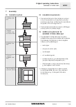
7.1 

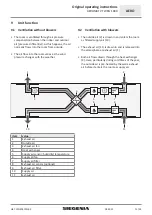
Installation options

Installation.in.the.

wall

AEROMAT VT

Concealed.

installation.in.the.

wall.with.wall.duct

AEROMAT VT

Installation.in.the.

lintel

AEROMAT VT

Concealed.

installation.in.the.

lintel

AEROMAT VT

Vertical.installation.

next.to.the.window

AEROMA

T VT

7.2 

Installation requirements

• 

The.position.from.which.the.outdoor.air.is.drawn.

in.must.be.selected.in.such.way.that.any.nearby.

emission.sources.have.as.little.impact.as.possible.on.

the.quality.of.the.air.being.drawn.in.

• 

The.maximum.permissible.area.load.is.1,000.kg.per.

running.metre.of.ventilator.length.

7.3 

Additional requirements for


AEROMAT VT WRG 1000

 smart

• 

The.

AEROMAT VT WRG 1000

.smart.should.be.

installed.to.be.as.free.from.interference.as.possible..

The.following.interferences.can.have.a.negative.

influence.on.the.WLAN.signal:

– 

water.pipes

– 

stone.and.concrete.walls

– 

metal.objects

– 

air.conditioning.units

– 

wireless.devices.(e..g..radio.telephones,.baby.

monitors,.Bluetooth.loudspeakers,.etc.)

– 

WIFI.networks.on.the.same.wireless.channels.(e..

g..the.neighbour's.WIFI.router)

• 

If.energy-carrying.cables.are.routed.in.parallel.

to.data.cables.(ISDN,.DSL,.etc.),.this.could.lead.

to.interference.e.g..in.the.speed.of.the.data.

transmission.

Summary of Contents for AERO AEROMAT VT WRG 1000 smart

Page 1: ...ORIGINAL OPERATING INSTRUCTIONS AERO Sound absorbing ventilator AEROMAT VT WRG 1000 Window systems Door systems Comfort systems...

Page 2: ......

Page 3: ...13 11 1 Notes on calibration 13 11 2 Performance of calibration 13 12 OPERATION 14 12 1 Ventilation without blowers 14 12 2 Ventilation with blowers 14 12 3 Adjustment of the blower level using the me...

Page 4: ...sition horizontal Weather grille HW g concealed installation in the wall installation position horizontal Weather grille CW installation position horizontal Weather grille HS installation position ver...

Page 5: ...ectrically operated unit Risk of fatal injury from electric shock or fire To prevent personal injury or damage to property always comply with the following instructions all work on a 230 V AC mains po...

Page 6: ...start instructions for the SIEGENIA Comfort app are located behind the front panel To open the front panel see page 17 2 3 1 6 Equipment name AEROMAT VT WRG 1000 AEROMAT VT WRG 1000 smart Operation vi...

Page 7: ...on the quality of the air being drawn in The maximum permissible area load is 1 000 kg per running metre of ventilator length 7 3 Additional requirements for AEROMAT VT WRG 1000 smart The AEROMAT VT...

Page 8: ...ing to the installation location it is therefore necessary to adhere the AEROMAT VT WRG 1000 at points where rain could permeate AEROMAT VT Film Adhesive tape Exterior insulation Adhesive tape Example...

Page 9: ...EGENIA aluminium mounting angles AEROMAT VT WRG 1000 with weather grille CW AEROMAT VT WRG 1000 with weather grille HW Dimension Meaning a Assembly area for bracket b Screw and drilling area e g for w...

Page 10: ...f the AEROMAT VT WRG 1000 is connected directly to the 230 V AC mains power supply the customer must install a mains isolator 8 1 1 Wiring diagram series switch L1 N 4 3 2 1 S1 PE N L1 S2 black AEROMA...

Page 11: ...blowers The outside air 2 is drawn in and enters the room as filtered supply air 10 The exhaust air 11 is drawn in and is released into the atmosphere as exhaust air 1 Both air flows drawn through th...

Page 12: ...required blower level is determined by means of the air quality TVOC Total Volatile Organic Compounds are volatile organic compounds in gaseous form e g ethanol carbon monoxide methane butane and ciga...

Page 13: ...lasts 24 hours The automatic mode already functions during the calibration AEROMAT VT WRG 1000 smart the air quality is already displayed during the calibration in the SIEGENIA Comfort app The accurac...

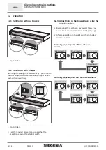
Page 14: ...ers 2 Set the required blower level using either the membrane key or the external switch 12 3 Adjustment of the blower level using the membrane key By pressing the membrane key several times you can a...

Page 15: ...tch again takes you back to the required blower level External switches must be provided by the customer The displayed switches are only recommendations Series switch Blower level 0 Blower level 1 Blo...

Page 16: ...e app Blower performance The blower performance can be set manually On application of the automatic mode the manually adjusted blower performance is overridden Automatic mode For information on the au...

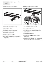
Page 17: ...1000 with a cloth moistened with a mild soap solution or cleaning agent 13 2 Maintenance intervals Changing the filter Replace filter every 12 months or when the filter change indicator lights up Fil...

Page 18: ...Insert the new supply air filter 6 Reassemble the AEROMAT VT WRG 1000 in the reverse order 13 5 Replacing the exhaust air filter 2 3 1 Remove the front panel see page 17 2 Remove the retention spring...

Page 19: ...present 7 Remove the heat exchanger and clean it thoroughly under running water 8 Leave the heat exchanger to dry completely 9 Insert the cleaned heat exchanger so that it is sealed on all sides in t...

Page 20: ...the home network no WIFI connection to the smartphone tablet restart smartphone tablet No WIFI connection to the AEROMAT VT WRG 1000 smart Reset on the AEROMAT VT WRG 1000 smart 1 Press membrane key 3...

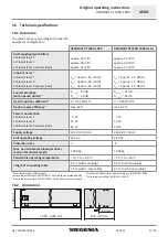
Page 21: ...dB Dn e w 54 dB Heat transition coefficient4 U 0 55 W m K U 0 55 W m K Heat recovery efficiency 5 max 62 max 62 Power consumption at blower level 1 at blower level 2 at blower level 3 power level 5 W...

Page 22: ...j Noise level 44 dB A 44 dB A k Relative air flow rate 38 m h 38 m h l Relative pressure differential m Specific input power 0 3 W m h 0 34 W m h n Control factor control typology 0 65 1 21 0 65 1 21...

Page 23: ...N 60335 1 2012 A11 2014 EN 62233 2008 c 2014 53 EC RED Directive c1 Electromagnetic compatibility EN 301489 1 V 1 9 2 EN 301 489 17 V 2 2 1 EN 61000 3 2 2014 EN 61000 3 3 2013 c2 Electrical safety Est...

Page 24: ...H47 FENS037EN 03 www siegenia com...

Reviews: