background image

H39.MFVRS004EN-00

02.2019

13/64

Assembly instructions

Multi-point locks, key operated

BS 230X, BS 250X, BS 260X

3.1.4 

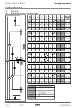
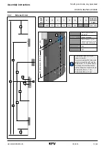
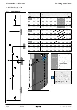
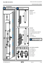
Main lock types, key-operated

Variable dimensions in mm

Main lock type

Cylinder lock  

PZ/RZ

PZ dimen-

sion 

[E]

Backset 

[D]

Rear backset 

[L]

Deadbolt pro-

jection


[R]

[M]

[N]

[O]

[P]

[Q]

[S]

V

PZ

72

55, 65, 70, 80

17.5

20

29

57.5

12.5

51.5

47

12

V

RZ

74

55, 65, 70, 80

17.5

20

29

57.5

12.5

49.5

47

12

H

PZ

85

25

17.5

Without dead-

bolt

36

50.5

19.5

31.5

52

8

H

PZ

85

30

17.5

10

36

50.5

19.5

31.5

52

8

H

PZ

85

35

17.5

16

36

50.5

19.5

31.5

54

12

H

PZ

85

40 - 80

17.5

20

36

50.5

19.5

31.5

54

12

H

PZ

88

35

17.5

16

33

53.5

16.5

31.5

51

12

H

PZ

88

40 -80

17.5

20

33

53.5

16.5

31.5

51

12

H

PZ

92

25

17.5

Without dead-

bolt

29

57.5

12.5

31.5

45

8

H

PZ

92

30

17.5

10

29

57.5

12.5

31.5

45

8

H

PZ

92

35

17.5

16

29

57.5

12.5

31.5

47

12

H

PZ

92

40 -80

17.5

20

29

57.5

12.5

31.5

47

12

H

RZ

94

35

20.3

16

29

57.5

12.5

29.5

47

12

H

RZ

94

40 -80 

20.3

20

29

57.5

12.5

29.5

47

12

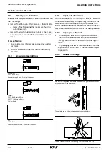
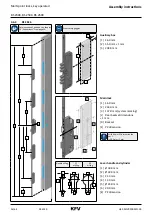
Figure: PZ

Figure: RZ

D

L

R

S

M

E

O

N

Q

P

6,5

53,5

3*

milling dimensions

system 

marker

D

L

E

P

*  This dimension refers to a flat face plate 3 mm, galvanized steel.


  This dimension and other dependent dimensions could change if other faceplates are used.

Summary of Contents for BS 230X

Page 1: ...SEMBLY INSTRUCTIONS KFV BS 230X BS 250X BS 260X T2 Safety lock Additional deadbolt lock TR Extension pieces BV 1X00 1 BV 1X00 2 Multi point locks Key operated Comfort systems Door systems Window syste...

Page 2: ...02 2019 2 64 H39 MFVRS004EN 00 Multi point locks key operated Assembly instructions BS 230X BS 250X BS 260X...

Page 3: ...ocket for the additional deadbolt lock TR 24 4 6 3 BS 23 25 2604 25 4 6 4 BS 2616 26 4 7 Installing the multi point lock 27 4 8 Extension pieces 28 4 8 1 Milling the door leaf for extension pieces BV...

Page 4: ...et rooms or rooms in which the air contains ag gressive or corrosive components Foreign objects and or materials which impede or prevent proper use must not be placed within the opening range the lock...

Page 5: ...sensitive components and must therefore be handled with care For example they must not be thrown hit hard or bent Do not carry the door by the lever handle or hard ware when transporting it 1 7 Dimens...

Page 6: ...Do not drill through the door leaf in the area of the gear box when the lock or the multi point lock is installed The spindle must not be hit through the lock nut with force The door leaf must not be...

Page 7: ...exerted on the lever handle only in the normal direction of rotation A maximum force of 150 N may be applied to the lever handle in the direction of actuation The lock or multi point lock must be lock...

Page 8: ...1 Personal protective equipment You will need the following protective equipment when assembling multi point service locks Safety shoes Protective gloves Protective goggles 2 2 Heavy components When w...

Page 9: ...0 with round bolt hook bolt combination 5 The multi point locks with two auxiliary boxes can be upgraded with the T2 safety lock 6 or the additional dead bolt lock TR 7 The multi point lock BS 2616 8...

Page 10: ...3 2170 760 980 385 952 355 2171 2400 K038 1629 760 605 385 892 355 1755 1880 K002 1754 760 730 385 892 355 1881 2170 K054 2004 760 980 385 892 355 2171 2400 K296 1442 760 355 892 1505 1754 K298 1692 7...

Page 11: ...400 Not available with hole group T0 Dimensions I K Can be shortened X All dimensions from the system marking X to the centre of the auxiliary box M 36 0 N 50 5 All dimensions given refer to the syste...

Page 12: ...48 359 188 1 2170 B253 2170 756 984 381 948 359 2171 2400 B325 2170 756 359 381 1046 635 160 1535 1785 B327 2170 756 609 381 1046 359 385 160 1786 1910 B002 2170 756 734 381 1046 359 260 160 1911 2170...

Page 13: ...35 17 5 16 36 50 5 19 5 31 5 54 12 H PZ 85 40 80 17 5 20 36 50 5 19 5 31 5 54 12 H PZ 88 35 17 5 16 33 53 5 16 5 31 5 51 12 H PZ 88 40 80 17 5 20 33 53 5 16 5 31 5 51 12 H PZ 92 25 17 5 Without dead b...

Page 14: ...9 14 64 H39 MFVRS004EN 00 Multi point locks key operated Assembly instructions BS 230X BS 250X BS 260X 3 1 5 Auxiliary box BS 2300 BS 2500 BS 2600 3 1 6 T2 Safety lock 8 5 3 1 7 Additional deadbolt lo...

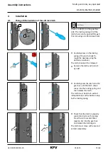
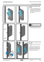
Page 15: ...the latch shank th rough the opening using the slotted screwdriver The latch shank will be released f f Remove the latch and rotate it by 180 CLICK f f Carefully press the latch into the gear box unt...

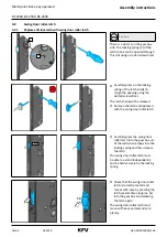
Page 16: ...the slotted screwdriver The latch shank will be released f f Remove the latch and replace it with the swing door roller latch CLICK f f Carefully press the swing door roller latch into the gear box u...

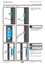
Page 17: ...agon wrench into the latch shaft through the hole in the centre part max 11 9 mm min 3 4 mm The swing door roller latch may only be unscrewed to the defined maxi mum value The position of the swing do...

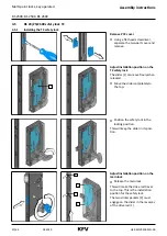
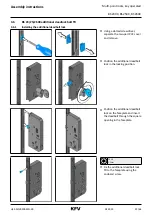
Page 18: ...h shank will be visible in the opening of the gear box f f Press on the locking spring of the latch shank through the opening using a slotted screwdriver The latch shank will be released f f Remove th...

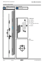
Page 19: ...2 3 Auxiliary box 1 16 0 mm 2 42 5 mm 1 mm 3 164 0 mm 1 2 D E 3 L Main lock 1 16 0 mm 2 234 0 mm 3 137 0 mm system marking L Rear backset dimensions 1 mm D Backset E PZ dimension All dimensions of th...

Page 20: ...ion position on the T2 safety lock The slider 1 can move freely when released f f Move the slider completely to the top f f Position the safety lock in the locking position This will keep the slider i...

Page 21: ...e and couple the striker packers of the slider with the drive rod in the recesses TX 10 1 5 Nm f f Fix the T2 safety lock to the face plate using the enclosed screws 1x 2 1 Releasing the T2 safety loc...

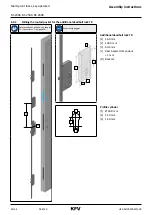
Page 22: ...instructions BS 230X BS 250X BS 260X 4 5 2 Milling the routed pocket for the T2 safety lock see chapter 3 1 Size variants from page 10 Wear safety goggles X H 1 2 D 3 L T2 Safety lock 1 16 0 mm 2 134...

Page 23: ...onal deadbolt lock f f Using a slotted screwdriver separate the two part PVC cover and remove f f Position the additional deadbolt lock in the locking position f f Position the additional deadbolt loc...

Page 24: ...illing the routed pocket for the additional deadbolt lock TR Determination of position see chapter 3 1 Size variants from page 10 Wear safety goggles X H 1 2 D 3 L Additional deadbolt lock TR 1 16 0 m...

Page 25: ...X X H F X 1 2 3 Auxiliary box 16 0 mm 42 5 mm 1 mm 164 0 mm 1 2 D E 3 L Main lock 1 16 0 mm 2 234 0 mm 3 137 0 mm system marking L Rear backset dimensions 1 mm D Backset E PZ dimension All dimensions...

Page 26: ...es A C B G K I X X H F X 1 2 3 Auxiliary box 1 16 0 mm 2 55 0 mm 1 mm 3 204 0 mm 1 2 D E 3 L Main lock 1 16 0 mm 2 234 0 mm 3 137 0 mm system marking L Rear backset dimensions 1 mm D Backset E PZ dime...

Page 27: ...structions Multi point locks key operated BS 230X BS 250X BS 260X 4 7 Installing the multi point lock f f Insert the multi point lock in the milled door leaf f f Screw the multi point lock to the door...

Page 28: ...cropping possibility Achievable position of the auxiliary box max cropping possibility Achievable position of the auxiliary box B296 605 180 725 1330 90 819 1424 B298 355 180 975 1330 90 1069 1424 B00...

Page 29: ...key operated BS 230X BS 250X BS 260X 4 8 1 Milling the door leaf for extension pieces BV 13 15 1600 1 BV 13 15 1600 2 Determination of position see chapter 4 8 Extension pieces from page 28 Wear safet...

Page 30: ...the top auxiliary box of the multi point lock and the auxiliary box of the extensi on piece using a drive rod f f Bring the locking elements of the multi point lock into the release position f f Loose...

Page 31: ...S 250X BS 260X 1 2 f f Replace the auxiliary box on the face plate f f Ensure the proper coupling of the slider packer of the slider 1 with the recess of the drive rod 2 Use the new screws enclosed Th...

Page 32: ...e chapter 4 8 Extension pieces from page 28 Wear safety gloves 2 1 1 f f Mark the top projection 1 of the extension piece f f Crop the projection and deburr the sawn edges 2 f f Mark the projection 2...

Page 33: ...instructions Multi point locks key operated BS 230X BS 250X BS 260X 4 9 Installing the multi point lock and extension piece f f Insert the multi point lock in the milled door leaf Adjust the position...

Page 34: ...02 2019 34 64 H39 MFVRS004EN 00 Multi point locks key operated Assembly instructions BS 230X BS 250X BS 260X f f Fix the multi point lock using all screws provided...

Page 35: ...230X BS 250X BS 260X Hold the multi point lock firmly during the installation f f Remove the screws except for two screws at the bottom end of the face plate f f Loosen the two remaining screws to suc...

Page 36: ...r any circumstances f f Carefully angle the drive rod away from the face plate 1 2 f f Guide the toothed shoe 1 of the extension piece at a right angle to the drive rod 2 of the multi point lock 1 Do...

Page 37: ...sembly instructions Multi point locks key operated BS 230X BS 250X BS 260X f f Insert the multi point lock together with the extension piece into the routed po ckets f f Push the cover plate down ward...

Page 38: ...H39 MFVRS004EN 00 Multi point locks key operated Assembly instructions BS 230X BS 250X BS 260X f f Fix the multi point lock and the extension piece using all screws provided f f Fix the cover plate w...

Page 39: ...apter 3 1 4 Main lock types key operated from page 13 Dismount the multi point lock before drilling 4 10 1 Mounting the handle set Marking and drilling the holes f f With the multi point lock installe...

Page 40: ...ock TR Marking and drilling the holes f f With the multi point lock installed adjust the drilling template enclo sed with the hardware on the cylinder lock and mark the positions of the holes f f Dism...

Page 41: ...enclo sed assembly instructions of the producer 4 11 Milling the frame 4 11 1 Assembly specifications for SKG certified frame parts The dimensions for the vertical position must be exactly adhered to...

Page 42: ...ry box E8QH Locking rail Contact the KFV customer service to find out the cutting dimensions for other frame parts or locking rails Q adjustment of the auxiliary boxes 1 21 0 mm 2 135 0 mm 3 Component...

Page 43: ...riker plate Safety lock E8QT2H Locking rail with T2 Contact the KFV customer service to find out the cutting dimensions for other frame parts or locking rails Bolt casing of the T2 safety lock 1 21 0...

Page 44: ...riants from page 10 Always use safety goggles for milling work H X 1 3 2 The cutting dimensions given refer to 23xx striker plate Additional deadbolt lock TR Contact the KFV customer service to find o...

Page 45: ...to E8H striker plate Main lock Q striker plate Auxiliary box E8QH Locking rail Contact the KFV customer service to find out the cutting dimensions for other frame parts or locking rails Q adjustment o...

Page 46: ...ons given refer to EQH Locking rail Contact the KFV customer service to find out the cutting dimensions for other frame parts or locking rails Auxiliary box with six round bolts deadbolt backing 1 22...

Page 47: ...etermination of position see chapter 4 8 Extension pieces from page 28 Always use safety goggles for milling work O P X 1 3 2 The cutting dimensions given refer to Q striker plate Auxiliary box Contac...

Page 48: ...250X BS 260X 4 11 8 Assembling the frame parts Horizontal adjustment of the frame parts is performed in accor dance with the system axis f f Insert the locking rail or the striker plates into the rout...

Page 49: ...00031 C D RC2 RC3 3 pce 4 0x40 mm 3 pce 4 5x45 mm SKH certified Frame part for auxiliary box with hook bolt 2500 267 2W RC2 RC3 2 pce 4 0x40 mm 2 pce 4 5x45 mm SKH certified Frame part for auxiliary...

Page 50: ...ap Observe the assembly and operating instructions for the door hinges 1 f f In accordance with the enclosed assembly instruc tions of the door hinge manufacturer adjust the airgap 1 between the facep...

Page 51: ...door The latch must engage in the AT piece 1 and the door must remain locked If the latch does not engage or if the pressure on the door seal is too high the AT piece must be adjusted in the directio...

Page 52: ...he door and check whether the latch engages properly Repeat the adjustments if neces sary Day latch 1 T 10 The day latch differs from the AT piece by means of a sliding handle 1 releasable fitting par...

Page 53: ...he door on the frame seal is too low the Q adjustment must be moved in the direction of the frame seal If the contact pressure of the door on the frame seal is too high the Q adjustment must be moved...

Page 54: ...BS 260X 1 f f Turn the two eccentric screws 1 to the left or right up to 90 T 10 1 3 Nm f f Tighten the three fixing screws of the Q adjustment firmly 2x f f Close the door and lock with a double turn...

Page 55: ...h f f Let go of the lever handle The lever handle must return to its original position by itself and the latch must project completely Check the functioning of the latch with the key cylinder operated...

Page 56: ...ing elements of the auxiliary boxes must extend completely and with ease Checking the counter pressure retention f f Try to press back the locking elements manually The locking elements must not move...

Page 57: ...Adjust the AT piece in the direc tion of the frame Check the release of the latch with the lever handle f f Activate the lever handle and open the door The latch must retract completely and release th...

Page 58: ...ements of the auxiliary boxes must retract completely and with ease f f Open the door The door must open easily 5 3 Check T2 safety lock 1 3 2 Check lock f f Move the turn lock 1 into the locking posi...

Page 59: ...safety catch must remain in position and the door must open easily and fully 1x Check the release with the key f f Turn the key with a single turn out of the release position into the locking positio...

Page 60: ...te the lever handle or turn the key of the main lock to the release position It must be impossible to open the door Check the withdrawal of the key f f Turn the key of the additional deadbolt lock to...

Page 61: ...der lock If the key still cannot be pulled out the multi point lock must be checked by KFV 6 3 Sluggishness during locking and release f f Check the adjustments of the AT piece see chapter 4 13 1 Adju...

Page 62: ...catch the additional deadbolt lock TR must be checked by KFV 6 5 Functional disorder of the additional deadbolt lock TR Sluggishness during locking and release f f Dismount the multi point lock and l...

Page 63: ...H39 MFVRS004EN 00 02 2019 63 64 Assembly instructions Multi point locks key operated BS 230X BS 250X BS 260X...

Page 64: ...www siegenia com H39 MFVRS004EN 00...

Reviews: