background image

Summary of Contents for GENIUS 2.2 PANIC

Page 1: ...ASSEMBLY INSTRUCTIONS DRIVE Electromechanical multi point lock GENIUS 2 2 PANIC Comfort systems Door systems Window systems...

Page 2: ......

Page 3: ...n 23 6 4 2 Via the analogue connection 24 6 5 Screwing on the multi point lock 25 7 FRAME SIDE ASSEMBLY 27 7 1 Milling the frame for 1 sash doors 27 7 2 Assembling the frame parts and magnet 28 7 2 1...

Page 4: ...ted in the operating instructions Keep a copy of the cover side with the attached sticker in a safe place Ein Unternehmen der SIEGENIA Gruppe D 42551 Velbert 0432 CPR 00048 01 02 EN 179 2008 37601342A...

Page 5: ...lectrical and mechanical tooling knowledge and skills with regard to the professional mounting of technical elements knowledge and skills with regard to the retrofit of mechanical security technology...

Page 6: ...ried out in compliance with the current German VDE regulations e g VDE 0100 and any relevant country specific requirements All pole safety isolation should be used when rout ing the power supply netwo...

Page 7: ...nt lock could be damaged if you drill through the door leaf in the area of the gear box Do not drill into the door leaf in the area of the gear box NOTICE Damage to the main lock The main lock of the...

Page 8: ...ion and loads of more than 150 N are applied to the lever handle in the direction of activation or if the lock is activated with foreign objects Only load the lever handle in the normal direction of r...

Page 9: ...vailable in 4 versions Functions GENIUS PANIC versions 1 sash CB 2 sash 2F E B E B Function E cylinder operated lock Function B switching function Opening via the profile cylinder Opening via an E but...

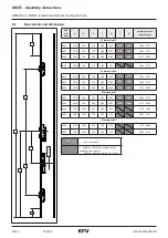
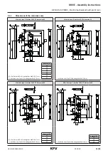
Page 10: ...1855 760 730 380 952 1881 2170 PZ dimension 94 B001 2170 760 730 380 1020 290 130 1881 2170 B002 2170 760 730 380 1050 290 160 1881 2170 B004 2400 760 980 380 1050 270 130 2171 2400 PZ dimension 72 B...

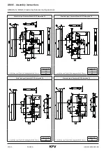
Page 11: ...92 1 D 1 Bei Dornma D 55 betr gt das Ma 220 7 mm bei Fallen vom Typ SL SA betr gt das Ma 10 mm Backset D 30 35 40 45 50 55 65 bei Fallen vom Typ SL SA betr gt das Ma 10 mm Main lock type P backset 35...

Page 12: ...e Z backset 55 and 65 PZ dimension 72 D D bei Fallen vom Typ SL SA betr gt das Ma 10 mm Backset D 55 65 bei Fallen vom Typ SL SA betr gt das Ma 10 mm Backset D 55 65 Main lock type P backset 65 PZ dim...

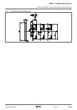
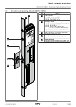
Page 13: ...13 45 13 45 01 2020 H39 ELEKS014EN 00 DRIVE Assembly instructions GENIUS 2 2 PANIC Electromechanical multi point lock 3 1 2 Dimensions of the auxiliary boxes...

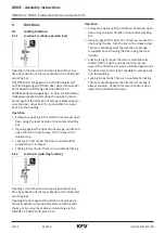
Page 14: ...any time by activation of the lever handle or the horizontal actuating bar Das ffnen der T r gegen die Fluchtrichtung ist erst nach Entriegelung und ffnen ber den Schl ssel oder der motorischen ffnun...

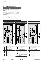
Page 15: ...e of operation switchover day night mode terminal 2 supply voltage 24 V DC terminal 3 supply voltage terminal 4 input for external unlocking signal at 24 V DC 1 seconds opening process terminal 7 feed...

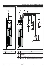
Page 16: ...tion GENIUS 2 2 PANIC via SI BUS connection GENIUS 2 2 PANIC via analogue connection GENIUS 2 2 PANIC via SI BUS connection and power supply via analogue connection 5 4 3 2 1 5 4 3 2 1 5 4 3 2 1 Item...

Page 17: ...BUS system 1 1s 1s V V L N PE V 14 A2 A1 12 11 A SI Bus Siemensstr 10 D 42551 Velbert GEN GEP 2 2 SN R1 R2 R3 24V DC 24V DC Input Output B C D 0 1 2 3 4 7 Power supply 1 2 3 4 5 Item Name 1 SI BUS ad...

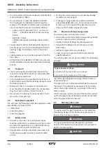
Page 18: ...justment accurately Remove any splinters from routed pockets after milling Do not overtighten the screws or insert them at an angle Once the multi point lock is installed do not per form mechanical wo...

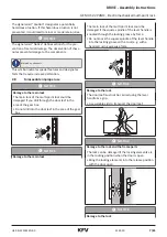
Page 19: ...e rear of the gear box f f Loosen the locking screws of the latch shaft with the PZ2 screwdriver until the latch can be pulled forwards and rotated by 180 f f Rotate the latch by 180 f f Press in the...

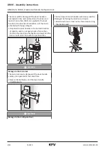
Page 20: ...of escape 1 2 SL 3 5 f f Loosen the cheese head screw for the adjustment of the direc tion escape with the slot screw driver 1 and remove the screw from the hole 2 2 1 f f F hren Sie die Zylinderkop f...

Page 21: ...anger of injury from swarf flying around rapidly During milling work there will be swarf flying around You could suffer eye injuries Wear protective goggles K I F B G A C 3 2 1 auxiliary box 1 16 0 mm...

Page 22: ...mechanical multi point lock K I F B G A C 3 2 1 GENIUS 2 2 PANIC 1 16 0 mm 2 55 0 mm 3 270 0 mm Lever handle milling Profile cylin der milling Round cylin der milling E 1 2 5 6 3 4 4 Lever handle and...

Page 23: ...File or line any sharp edges Route cables without kinking A SI Bus Siemensstr 10 D 42551 Velbert GEN GEP 2 2 SN R1 R2 R3 24V DC 24V DC Input Output B C D 0 1 2 3 4 7 Always route the cable to the GEN...

Page 24: ...3 GND Operating voltage 4 Yellow Green 4 input External unlocking signal 7 Violet Pink Feedback contact White Blue Shield for power supply Establish plug connection for GENIUS 2 2 PANIC 1 0 4 7 1 2 1...

Page 25: ...tening of the screws of the locking box and the GENIUS drive could lead to sluggishness of the mechanical system Both could cause malfunction and or failure Tighten the screws with 1 Nm manually 1 1 f...

Page 26: ...01 2020 26 45 H39 ELEKS014EN 00 DRIVE Assembly instructions GENIUS 2 2 PANIC Electromechanical multi point lock 10 x f f Screw the multi point lock to the door leaf...

Page 27: ...ng around You could suffer eye injuries Wear protective goggles F 1 mm C B M N X 2 3 1 The milling dimensions given refer to E8H striker plate Main lock Q striker plate auxiliary box E8QH locking rail...

Page 28: ...ivered ver sion the locking rail is predrilled 13 mm or marked at the relevant point or has a fastening hole at this point that must be drilled to 13 mm According to the profile of the locking rail an...

Page 29: ...2 Mounting the striker plates in PVC and aluminium frames f f Insert the striker plates into the intended millings f f Then screw the striker plates to the door frame 9 x Insert the oval magnet bush...

Page 30: ...IC Electromechanical multi point lock 7 2 3 Mounting the striker plates in timber frames f f Insert the striker plates into the intended millings f f Then screw the striker plates to the door frame 7...

Page 31: ...ons GENIUS 2 2 PANIC Electromechanical multi point lock 7 2 4 Mounting the locking rail f f Insert the locking rail plates into the intended millings f f Then screw the locking rail to the door frame...

Page 32: ...airgap Observe the assembly and operating instructions for the door hinges 1 f f In accordance with the enclosed assembly instruc tions of the door hinge manufacturer adjust the airgap 1 between the f...

Page 33: ...ose the door The latch must engage in the AT piece 1 and the door must remain locked If the latch does not engage or if the pressure on the door seal is too high the AT piece must be adjusted in the d...

Page 34: ...DRIVE Assembly instructions GENIUS 2 2 PANIC Electromechanical multi point lock T 10 2 5 Nm f f Tighten the two adjustment screws f f Close the door and check wheth er the latch engages properly Repea...

Page 35: ...of the door on the frame seal is too low the Q adjustment must be moved in the direction of the frame seal If the contact pressure of the door on the frame seal is too high the Q adjustment must be mo...

Page 36: ...int lock 1 f f Turn the two eccentric screws 1 to the left or right up to 90 T 10 1 3 Nm f f Tighten the three fixing screws of the Q adjustment firmly 2x f f Close the door and lock with a double tur...

Page 37: ...pletely Bring the key into the withdrawal position The latch must extend completely again after the key is released f f Turn the key in the cylinder lock in the unlocking direction switching function...

Page 38: ...tlessly replace the cylinder and repeat the test step If the profile cylinder functions faultlessly there is a mechanical disorder in the multi point lock 8 4 3 Malfunction of the magnetic sensor If t...

Page 39: ...knowledgement 5 x 1 s f f Press the button 5 times quickly in succession approx 1 second each time until the LED lights up light blue You will change to the main menu f f Every press of a button is ac...

Page 40: ...g tone f f Die T r noch nicht schlie en f f A continuous tone is sounded after approx 4 s f f Now close the door f f Adjustment of magnetic sensor follows This procedure can take a few seconds f f If...

Page 41: ...standby IST Type 30 mA Operating current for motor control IB Type 500 mA max 1000 mA Reverse polarity protection UVerp 50 V Output signal terminal 7 Switches actively against mass GND IKL7 20 mA Inpu...

Page 42: ...hould not be disposed of with household waste Comply with the current local and national regula tions The packaging consists of raw materials that can be recycled and can be taken to the local recycli...

Page 43: ...mbH Co KG Test and Certification Authority test report identification number FS 1708 336996 001 The incomplete machine may only be commissioned if it has been ascertained if required that the machine...

Page 44: ......

Page 45: ...www siegenia com H39 ELEKS014EN 00...

Reviews: