background image

DRIVE - Assembly instructions

GENIUS 2.2,  Electromechanical multi-point lock

02.2020

24/44

H39.ELEKS013EN-00

5.4.2 

Via the analogue connection

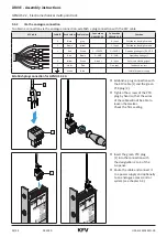
To obtain a connection via the analogue connection, establish a plug connection with the KFV cable.

KFV cable

Cable ID Band colour Cable colour

Connection 

GENIUS 2.2 A

Connection 

GENIUS 2.2 B

Function

0

1

+

-

4

7

0

Black

grey

-

0: input

Switchover day/night mode

1

Brown

Yellow

-

1: input

Switchover day/night mode

+

Red

White

2: + 24VDC

2: + 24VDC

Operating voltage (+) 24 V DC

-

Blue

Brown

3: - GND

3: - GND

Operating voltage (-) 

4

Yellow

Green

4: input

4: input

External unlocking signal

7

Violet

Pink

-

7: output

Feedback contact

White

Blue

-

-

Shield for power supply

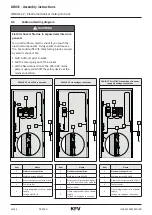
Establish plug connection for GENIUS 2.2 A

+


-


4


1

2

+


-


4


f

Establish a plug connection with 

the KFV cable [1] and the green 

PTR plug [2].


f

Tighten the screws of the PTR 

plug by hand so that the wires 

of the cable will not be able to 

loosen themselves. 


Check the firm seating.

+


-


4


1

+


-


4


f

Insert the green PTR plug 

[1] into the connection with 

the designation 2 to 4 of the 

A-opener.


f

Route the cable and connect it 

to a power supply and optionally 

to an analogue access control 

system (see chapter 4.3).

Summary of Contents for GENIUS 2.2

Page 1: ...ASSEMBLY INSTRUCTIONS DRIVE Electromechanical multi point lock GENIUS 2 2 Comfort systems Door systems Window systems...

Page 2: ......

Page 3: ...5 3 1 Change DIN orientation of the latch 20 5 3 2 Milling the door leaf 21 5 4 Routing and connecting cables 23 5 4 1 Via the SI BUS connection 23 5 4 2 Via the analogue connection 24 5 5 Screwing on...

Page 4: ...point lock for the motorised locking and unlocking of doors These operating instructions are an integral part of the GENIUS 2 2 and must be accessible to the target group all the time 1 3 Producer KFV...

Page 5: ...sional fixing of technical elements knowledge and skills with regard to the retrofit of mechanical security technology on window or door elements If the door elements are equipped with an electrome ch...

Page 6: ...ards and prohibit specific behaviour The warning notes are set up according to the following principle SIGNAL WORD Type and source of danger Explanation of the type and source of danger Measures for t...

Page 7: ...e NOTICE Damage to the lock The door leaf must not be carried using the lever handle as a grip as this could lead to damage Use suitable aids to transport the door leaf NOTICE Damage to the lock and t...

Page 8: ...main lock can be damaged if the lever handle and key are operated at the same time Never activate the key and the lever handle simultaneously NOTICE Damage to the multi point lock The multi point loc...

Page 9: ...ry boxes 1 GEN AS 2600 GEN AS 2500 GEN AS 2300 Variants of functions Functions GENIUS version EA EB CA CB Opening via the profile cylinder Opening via an E button optional Opening via an access contro...

Page 10: ...60 605 380 952 1755 1880 B166 1855 760 730 380 952 1881 2170 B253 2170 760 980 380 952 2171 2400 K038 1629 760 605 380 892 1755 1880 K002 1754 760 730 380 892 1881 2170 K054 2004 760 980 380 892 2171...

Page 11: ...s in versions CA and CB 2 21 5 mm for version EA 21 0 mm for version CA and CB for latches type FS the dimension is 12 mm Backset D 35 40 45 50 55 1 omitted for multi point locks in versions CA and CB...

Page 12: ...lock type K backset 35 50 PZ dimension 85 D 1 D for latches type FS the dimension is 12 mm Backset D 35 40 45 50 55 1 6 5 from backset 45 for latches type FS the dimension is 12 mm Backset D 35 40 45...

Page 13: ...13 44 DRIVE Assembly instructions GENIUS 2 2 Electromechanical multi point lock 13 44 02 2020 H39 ELEKS013EN 00 3 1 2 Dimensions of the auxiliary boxes...

Page 14: ...erminal D supply voltage 24 V DC 2 Analogue connection Terminal 2 supply voltage 24 V DC Terminal 3 supply voltage Terminal 4 input for external unlocking signal at 24 V DC 1 seconds opening process 3...

Page 15: ...de of operation switch day night mode Terminal 2 supply voltage 24 V DC Terminal 3 supply voltage Terminal 4 input for external unlocking signal at 24 V DC 1 seconds opening process Terminal 7 feedbac...

Page 16: ...GENIUS 2 2 via SI BUS connection GENIUS 2 2 via analogue connection GENIUS 2 2 via SI BUS connection and power supply via analogue connection 5 4 3 2 1 5 4 3 2 1 5 4 3 2 1 Item Name 1 Electromechanic...

Page 17: ...bert GEN 2 2 A SN R1 R2 R3 24V DC 24V DC Input n c B C D 0 1 2 3 4 7 n c n c SI BUS system 1 1s 1s V L N PE V A SI Bus Siemensstr 10 D 42551 Velbert GEN 2 2 A SN R1 R2 R3 24V DC 24V DC Input n c B C D...

Page 18: ...ystem 1 1s 1s V V L N PE V 14 A2 A1 12 11 A SI Bus Siemensstr 10 D 42551 Velbert GEN 2 2 B SN R1 R2 R3 24V DC 24V DC Input Output B C D 0 1 2 3 4 7 Power supply 1 2 3 4 5 Item Name 1 SI BUS adapter ca...

Page 19: ...justment accurately Remove any splinters from routed pockets after milling Do not overtighten the screws or insert them at an angle Once the multi point lock is installed do not per form mechanical w...

Page 20: ...e rear of the gear box f f Loosen the locking screws of the latch shaft with the PZ2 screwdriver until the latch can be pulled forwards and rotated by 180 f f Rotate the latch by 180 f f Press in the...

Page 21: ...ger of injury from swarf flying around rapidly During milling work there will be swarf flying around You could suffer eye injuries Wear protective goggles K I F B G A C 3 2 1 Auxiliary box 1 16 0 mm 2...

Page 22: ...020 22 44 H39 ELEKS013EN 00 K I F B G A C 3 2 1 GENIUS 2 2 1 16 0 mm 2 55 0 mm 3 270 0 mm Lever handle milling Profile cylin der milling Round cylin der milling E 1 2 5 6 3 4 4 Lever handle and cylind...

Page 23: ...le or line any sharp edges Route cables without kinking A SI Bus Siemensstr 10 D 42551 Velbert GEN 2 2 B SN R1 R2 R3 24V DC 24V DC Input Output B C D 0 1 2 3 4 7 Always route the cable to the GENIUS 2...

Page 24: ...voltage 24 V DC Blue Brown 3 GND 3 GND Operating voltage 4 Yellow Green 4 input 4 input External unlocking signal 7 Violet Pink 7 output Feedback contact White Blue Shield for power supply Establish p...

Page 25: ...KFV cable 1 and the green PTR plug 2 f f Tighten the screws of the PTR plug by hand so that the wires of the cable will not be able to loosen themselves Check the firm seating 1 0 4 7 1 1 0 4 7 f f I...

Page 26: ...5 Screwing on the multi point lock 1 f f Insert the multi point lock in the milled door leaf f f Adjust the multi point lock to the handle spindle 1 1 Ensure when you insert the GENIUS into the route...

Page 27: ...X 2 3 1 The milling dimensions given refer to E8H striker plate Main lock Q striker plate Auxiliary box E8QH Locking rail 23xx Bolt striker plate Contact the KFV customer service to find out the milli...

Page 28: ...sion the locking rail is predrilled 13 mm or marked at the relevant point or has a fastening hole at this point that must be drilled to 13 mm According to the profile of the locking rail and profile o...

Page 29: ...Mounting the striker plates in PVC and aluminium frames f f Insert the striker plates into the intended millings f f Then screw the striker plates to the door frame 9 x Insert the oval magnet bush wit...

Page 30: ...ck 02 2020 30 44 H39 ELEKS013EN 00 6 2 3 Mounting the striker plates in timber frame f f Insert the striker plates into the intended millings f f Then screw the striker plates to the door frame 7 x Th...

Page 31: ...cal multi point lock 31 44 02 2020 H39 ELEKS013EN 00 6 2 4 Mounting the locking rail f f Insert the locking rail plates into the intended millings f f Then screw the locking rail to the door frame If...

Page 32: ...gap Observe the assembly and operating instructions for the door hinges 1 f f In accordance with the enclosed assembly instruc tions of the door hinge manufacturer adjust the airgap 1 between the face...

Page 33: ...the door The latch must engage in the AT piece 1 and the door must remain locked If the latch does not engage or if the pressure on the door seal is too high the AT piece must be adjusted in the dire...

Page 34: ...ENIUS 2 2 Electromechanical multi point lock 02 2020 34 44 H39 ELEKS013EN 00 T 10 2 5 Nm f f Tighten the two adjustment screws f f Close the door and check wheth er the latch engages properly Repeat t...

Page 35: ...the door on the frame seal is too low the Q adjustment must be moved in the direction of the frame seal If the contact pressure of the door on the frame seal is too high the Q adjustment must be moved...

Page 36: ...EN 00 1 f f Turn the two eccentric screws 1 to the left or right up to 90 T 10 1 3 Nm f f Tighten the three fixing screws of the Q adjustment firmly 2x f f Close the door and lock with a double turn R...

Page 37: ...move sluggishly this can be due to various causes Side adjustment of the frame parts the sealing of the door leaf is influenced by distortion of the frame parts If this is excessive it can lead to slu...

Page 38: ...ylinder and repeat the test step If the profile cylinder functions faultlessly there is a mechanical disorder in the multi point lock f f Check whether the locking elements run smoothly into the frame...

Page 39: ...several times quickly in succession approx 1 second each time until the LED lights up light blue for GENIUS 2 2 EA CA 3 x and for GENI US 2 2 EB CB 5 x You will change to the main menu f f Every pres...

Page 40: ...ing tone f f Do not close the door yet f f A continuous tone is sounded after approx 4 s f f Now close the door f f Adjustment of magnetic sensor follows This procedure can take a few seconds f f If t...

Page 41: ...andby IST Type 30 mA Operating current for motor control IB Type 500 mA max 1000 mA Reverse polarity protection UVerp 50 V Output signal terminal 7 Switches actively against mass GND IKL7 20 mA Input...

Page 42: ...ld not be disposed of with household waste Comply with the current local and national regula tions The packaging consists of raw materials that can be recycled and can be taken to the local recycling...

Page 43: ...bH Co KG Test and Certification Authority test report identification number FS 1708 336996 001 The incomplete machine may only be commissioned if it has been ascertained if required that the machine i...

Page 44: ...www siegenia com H39 ELEKS013EN 00...

Reviews: