H39.MFVRS006EN-00
02.2019
11/44
Assembly instructions
Multi-point locks, key operated
BS 2100, BS 2800
3.1.2
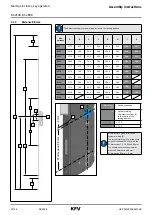
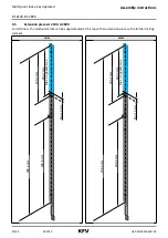
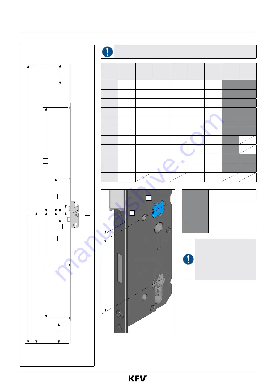
Distance 85 mm
A
X
C
H
B
G
F
I
K
N
M
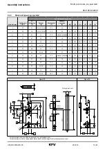
The dimensions apply to the multi-point lock in the locking position
Size
variants
A
B
C
F
G
H
I
K
R001
2170
816
817
403
1013
267
260
137
R002
2170
763
730
403
1043
267
310
219
R003
2170
816
660
403
1013
267
410
137
R004
2400
756
737
396
1043
274
534
226
R005
2170
873
730
403
1042
267
310
110
R014
2170
763
730
403
1013
267
340
189
R016
2170
963
910
403
1035
267
138
R023
2170
963
910
403
1042
267
131
R024
2170
763
810
403
1035
267
238
212
R025
2170
763
810
403
1043
267
230
220
K060
837
660
129
267
En
tfernung 85 mm
-7 mm
X
1
Dimensions
I + K
=
Can be shortened
X
=
System marking
All dimensions from [X]
to the centre of the
locking element
M
= 36.0
N
= 50.5
All dimensions given refer to the
system marking [X].
The system marking [X] is at the same
height as the handle nut [1] with the
PZ dimensions 72, 74, 92 and 94 mm.
The handle nut moves downwards
with the PZ dimension 85 mm.
PZ dimension 85 mm = -7 mm
PZ dimension 85 mm


