H39.MFVRS006EN-00
02.2019
13/44
Assembly instructions
Multi-point locks, key operated
BS 2100, BS 2800
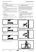
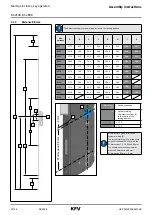
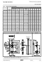
3.1.4
Main lock types, key-operated
Variable dimensions in mm
Main lock type
Cylinder lock
PZ/RZ
PZ
dimension
[E]
Backset
[D]
Rear backset
[L]
Deadbolt
projection
[R]
[M]
[N]
[O]
[P]
[Q]
[S]
V
PZ
72
55, 65, 70, 80
17.5
20
29
57.5
12.5
51.5
47
12
V
RZ
74
55, 65, 70, 80
17.5
20
29
57.5
12.5
49.5
47
12
H
PZ
85
25
17.5
without deadbolt
36
50.5
19.5
31.5
52
8
H
PZ
85
30
17.5
10
36
50.5
19.5
31.5
52
8
H
PZ
85
35
17.5
16
36
50.5
19.5
31.5
54
12
H
PZ
85
40 - 80
17.5
20
36
50.5
19.5
31.5
54
12
H
PZ
88
35
17.5
16
33
53.5
16.5
31.5
51
12
H
PZ
88
40 -80
17.5
20
33
53.5
16.5
31.5
51
12
H
PZ
92
25
17.5
without deadbolt
29
57.5
12.5
31.5
45
8
H
PZ
92
30
17.5
10
29
57.5
12.5
31.5
45
8
H
PZ
92
35
17.5
16
29
57.5
12.5
31.5
47
12
H
PZ
92
40 -80
17.5
20
29
57.5
12.5
31.5
47
12
H
RZ
94
35
20.3
16
29
57.5
12.5
29.5
47
12
H
RZ
94
40 -80
20.3
20
29
57.5
12.5
29.5
47
12
Figure: PZ
Figure: RZ
Fräsmaße
D
L
R
S
M
E
O
N
Q
P
6,5
53,5
3*
System-
markierung
D
L
E
P
* This dimension refers to a flat face plate 3 mm, galvanized steel.
This dimension and other dependent dimensions could change if other faceplates are used.
Milling dimensions
System
marker


