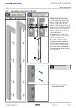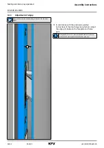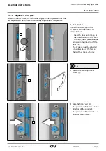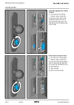
H39.MFVRS006EN-00
02.2019
29/44
Assembly instructions
Multi-point locks, key operated
BS 2100, BS 2800
4.9
Milling the frame
4.9.1
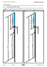
Frame milling for BS 2100 BS 2800
Determination of position, see chapter
Always use safety goggles for milling
work.
The frame parts are horizontally
adjusted according to the system axis.
M
N
X
The cutting dimensions given refer to:
E8H frame part: Main lock
Contact the KFV customer service
to find out the cutting dimensions
for other frame parts or locking rails.
Q adjustment of the auxiliary
boxes
[1]
21.0 mm
[2]
135.0 mm
[3] Component height plus 1 mm
1
5
2
3
4
3
1
5
2
3
4
3
AT piece and deadbolt lining
[1]
23.0 mm
[2]
72.0 mm
[3] Component height plus 1 mm
[4]
62.0 mm
[5]
16.0 mm
Milling is omitted for U-profiles from
a leg length of 6 mm and with use of the
AT piece series 118/119.
Day latch and deadbolt lining
[1]
23.5 mm
[2] 78.0 mm
[3] Component height plus 1 mm
[4]
62.0 mm
[5]
16.0 mm

