H39.MFVRS006EN-00
02.2019
33/44
Assembly instructions
Multi-point locks, key operated
BS 2100, BS 2800
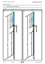
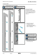
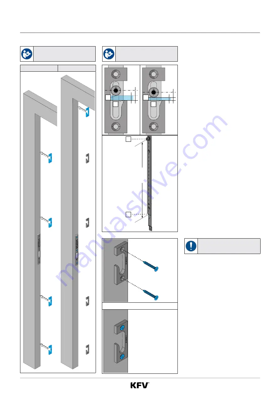
4.11.2 Assembling the frame parts for BS 2100
Determination of position, see chapter
Determination of position for A 2100,
see chapter 4.5 “Extension pieces
BS 2100
BS 2100 + A 2100
Min.
10 mm
195,
7 mm
185,
7 mm
Ma
x. K
ürzbark
eit
298,
6 mm
298,
6 mm
298.6
mm
Frame part for A 2100
The position of the cam on the
extension piece, measured from
the bottom edge of the extension
piece to middle of the cam, is
298.6 mm.
f
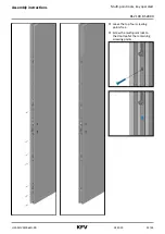
Position the frame parts
according to the SKG
specifications (see chapter
4.10.2 “Positioning of the frame
Use the prescribed screws for SKG
certified frame parts (see chapter 4.10
“Requirements for SKG certification” from
Use the screws recommended by KFV
for frame parts that are not SKG
certified (see chapter 1.10 “Screw
f
Fix the frame parts with the
corresponding screws.
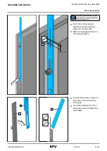
4.12
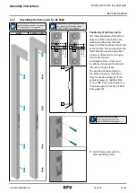
Assembling the frame parts for BS 2800
Determination of position, see chapter
Determination of position for A 2800
see chapter 4.5 “Extension pieces
BS 2800
BS 2800 + A 2800
2
1
10.5 mm
5 mm
2
1
8.5 mm
3 mm
Positioning of the frame parts
The interval between the bottom
edge [1] of the roller bolt (in the
release position) and the inlet
edge [2] of the frame part must not
exceed 5 mm. This ensures that the
roller bolt achieves the specified
minimum dimension for the grip
into the frame part.
An interval of min. 3 mm must
be adhered to prevent functional
disorders during release.
The position of the cam [3] on
the extension piece, measured
from the bottom edge [4] of the
extension piece to middle of the
cam, is 298.6 mm (see chapter 4.5
“Extension pieces A 2100, A 2800”
Min.
10 mm
195,
7 mm
185,
7 mm
Ma
x. K
ürzbark
eit
298,
6 mm
298,
6 mm
298.6
mm
4
3
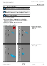
Use the screws recommended
by KFV (see chapter 1.10 “Screw
f
Fix all frame parts with the
corresponding screws.


