3
Last update: 01.08.2013
Assembly instructions
GENIUS
Explanation of symbols
Milling cutter or drill diame-
ter
Groove depth from profile
Groove length
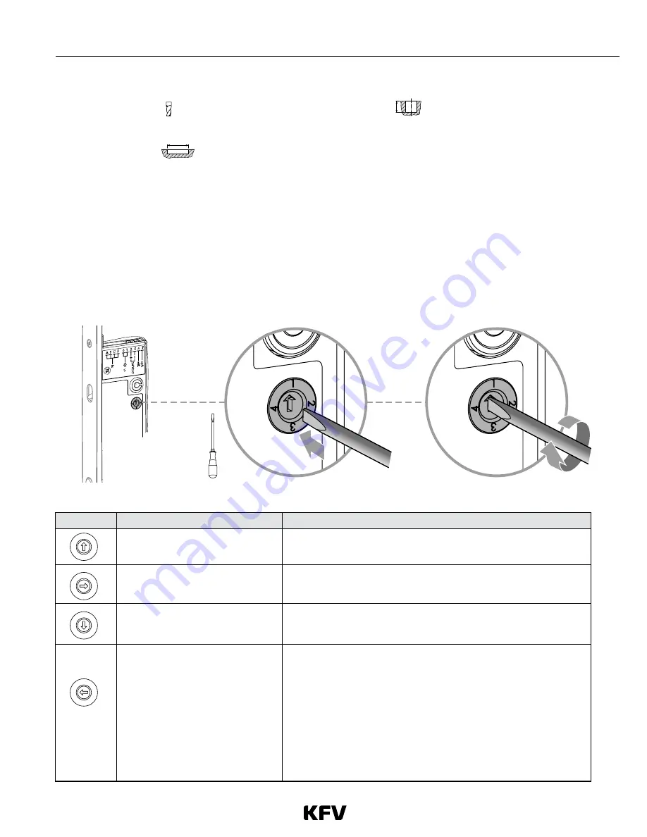
Rotary switch (optional signal outputs)
•
The rotary switch can only be operated when the lock is not installed.
•
The rotary switch is used to control the optional signal output, terminal 7. The output must not be subjected to a cur-
rent of more than 20 mA.
•
The rotary switch on the type B GENIUS door lock is used, if desired, to define the lock or door status that should
trigger the optional signal output.
•
Via an external relay (a 24 V DC coupling relay, available as a KFV accessory) connected to terminal 7, the GENIUS
door lock can be linked to other systems, e.g. alarm systems and hinged door drives.
Fig. 1: Rotary switch
Position
Status
Comments
The lock is fully locked and the door
is shut.
•
For use in conjunction with alarm systems.
› Terminal 7 is connected to negative (-) ground.
The door is shut
•
For use in conjunction with monitoring by a porter.
› Terminal 7 is connected to negative (-) ground.
The latch is drawn into the cylinder
operated lock
•
For use in conjunction with a hinged door drive.
› Terminal 7 is connected to negative (-) ground.
Can be used to arm/disarm a con-
nected alarm system
•
Controlled using a 2-channel infra-red access key*
•
In order to keep the alarm system armed in the event of a power
failure, the terminal is connected to negative/ground when the
alarm is disarmed.
› Alarm disarmed = terminal 7 = negative -- relay on
› Alarm armed = terminal 7 = high resistance -- relay off
•
The break contact of the relay must be used to switch on the
alarm system.
*See GENIUS operating instructions for details of how to do this
1
2
3
4
1
2
3
4
1
2
3
4
1
2
3
4
Summary of Contents for KVF Genius
Page 2: ......
Page 15: ...13 Last update 01 08 2013 Assembly instructions GENIUS ...


